STATUS
FLUE 1
AUX
FLUE 2
TEMP
C
o
m
b
u
s
t
i
o
n
A
n
a
l
y
z
e
r
C161
C
O
C
O
2
T
E
M
P
STATUS
FLUE 1
AUX
FLUE 2
TEMP
C
o
m
b
u
s
t
i
o
n
A
n
a
l
y
z
e
r
C161
C
O
C
O
2
T
E
M
P
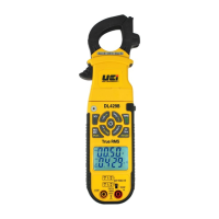
COMBUSTION ANALYSIS
T2 T1
Insert flue probe into stack.
Adjust cone so the probe tip is
approximately at the center of
the stack.
Insert flue probe into combustion
input. Insert K-type temperature
probe into input T1.
Rotate function rotary dial to
FLUE 1 for Flue Test Screen 1
parameters.
STATUS
FLUE 1
AUX
FLUE 2
TEMP
C
o
m
b
u
s
t
i
o
n
A
n
a
l
y
z
e
r
C161
C
O
C
O
2
T
E
M
P
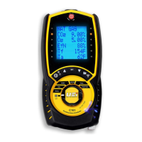
Flue 1 displays CO2, O2, Gross
Efficiency, Flue temperature,
Inlet temperature.
Rotate the function rotary dial
to FLUE 2 for Flue Test Screen 2
parameters.
STATUS
FLUE 1
AUX
FLUE 2
TEMP
C
o
m
b
u
s
t
i
o
n
A
n
a
l
y
z
e
r
C161
C
O
C
O
2
T
E
M
P
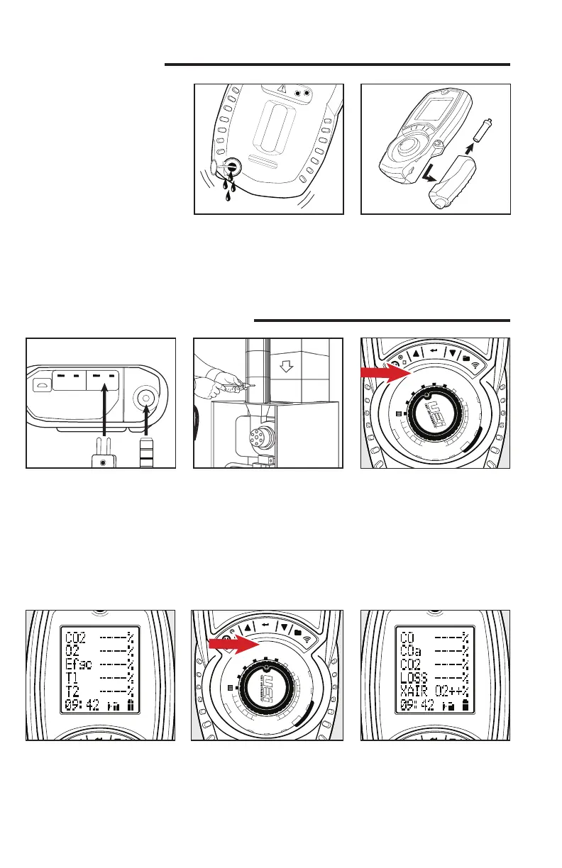
Flue 2 displays CO (ppm), Losses
calculated, Excess air %. Make
any adjustments needed for
proper Combustion and wait for
analyzer to display change in
readings. (Repeat as necessary).
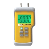
BEFORE TESTING
Remove the rubber boot and red
drain plug. Allow the water to
drain out. Re-insert the rubber
plug and replace boot cover.
Remove protective rubber boot.
Remove water trap from analyzer.
Remove particle filter from
spigot and replace with new
one. Reattach trap and boot.
CHECKLIST
oClean particle filter
oWater trap and probe line are
free of water
oAll hose and thermocouple
connections are properly
secured
oWater trap is fitted correctly
oPower on and zero
oFlue gas probe is sampling
ambient FRESH air
NOTE: If there is no hole, check with service and installation instructions of appliance for best testing
method or check with your local authority on best practice
 Loading...