Introduction
The HA1 analyzes and tests hermetic compressors at up to 25 amps of
running current. Connects directly to the compressor motor eliminating the
r e f r i g e r ation system start ca p a c i t o r.
Features include
• 3 Ranges of 250 V AC starting capacitors between 88-301 MFD
• Dual voltage operation of 120/240 V AC
• Indicates continuity & ground faults in motor windings
with LED lights
• Free locked rotors by reversing motor action
• Convenient breakout jacks for measuring voltage and resistance
Safety Notes
Before using this instrument, read all safety information carefully. In
this manual the word "WARNING" is used to indicate conditions
or actions that may pose physical hazards to the user. The word
"CAUTION" is used to indicate conditions or actions that may
damage this instrument.
• Do not attempt to measure any voltage that exceeds the
ca t e g o ry based rating of this meter
• Do not attempt to use this instrument if either the meter or the test
leads have been damaged. Turn it in for repair at a qualified
repair facility
• Ensure instrument leads are fully seated by making a quick continuity
check of the leads prior to making voltage measurements
• Keep your fingers away from the test lead’s metal probe
contacts when making measurements. Always grip the leads behind
the finger guards molded into the probes
• Use a current clamp adapter when measuring current that may
exceed 10 amps. See the accessories in UEi’s full-line ca t a l o g
• Do not open the instrument to replace batteries or fuses while the
probes are connected
WARNING!
Exceeding the specified limits of this instrument is dangerous and can
expose the user to serious or possibly fatal injury.
• Voltages above 60 volts DC or 25 volts AC may constitute a
serious shock hazard
• Always turn off power to a circuit (or assembly) under test
before cutting, unsoldering, or breaking the current path -
Even small amounts of current can be dangerous
• Always disconnect the live test lead before disconnecting the
common test lead from a circuit
• In the event of electrical shock, ALWAYS bring the victim to
the emergency room for evaluation, regardless of the victim’s
apparent recovery - Electrical shock can cause an unstable heart
rhythm that may need medical attention
• Higher voltages and currents require greater awareness of
physical safety hazards - Before connecting the test leads; turn
off power to the circuit under test; set the instrument to the
desired function and range; connect the test leads to the
instrument first, then to the circuit under test. Reapply power
• If any of the following indications occur during testing, turn
off the power source to the circuit under test:
• Arcing
• Flame
• Smoke
• Extreme Heat
• Smell of Burning Materials
• Discoloration or Melting of Components
CAUTION!
Do not attempt to remove the instruments leads from the circuit under
test. The leads, the meter, or the circuit under test may have degraded
to the point that they no longer provide protection from the voltage and
current applied. If any of these erroneous readings are observed,
disconnect power immediately and recheck all settings and connections
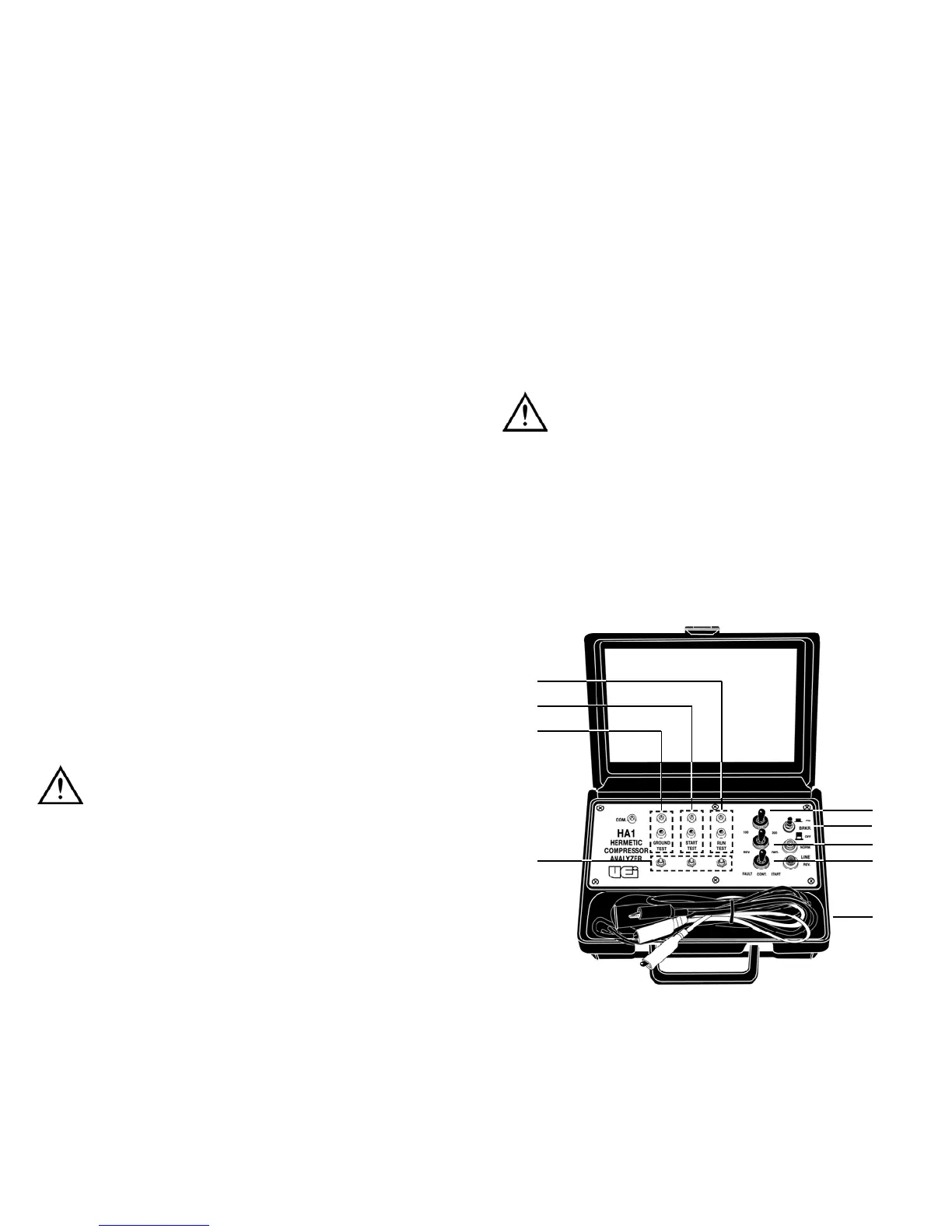
C o n t r ols and Indicators
1. PWR Breaker: This is a combination 25A circuit breaker and a
P O W ERON switch.
2. CAP 10 0 / 3 0 0 / 2 0 0 : Selects one of the three starting capacitor ra n g e s :
Position Range
100MFD 88-108MFD
200MFD 161-193MFD
300MFD 249-301MFD
HA1-MAN P. 1
1
2
3
4
5
6
7
8
9

 Loading...