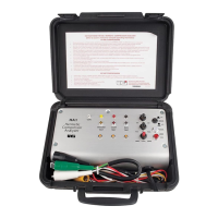
9. Test Jacks: The four test jacks are connected directly to the test
cable of the corresponding color: COMMON = white,
GROUND = yellow, START = red, and RUN = black. The purpose
of the test jacks is to facilitate resistance and voltage readings by
enabling voltmeter/ohm meter test leads to be connected to the
compressor motor circuit by inserting them into the appropriate
jack at the HA1 front panel.
*Since this cable is an “artificial” ground line it is colored yellow
instead of green.
Operating Instructions
NOTE: Every effort has been made to make the HA1 a safe and
versatile tester. However, under some circumstances line voltage may
be present on the HA1 test cables when the control switches are in the
OFF position. For this reason it is very important to read and become
familiar with the section on operation.
The following procedures have been detailed so a thorough
understanding of the operation sequence may be gained. In practice,
the following tests may be performed very quickly.
110 V AC Operation
CAUTION!
The HA1 is wired so that the white COMMON test cable is connected
to the neutral side of the line. The red START and black RUN cables
are connected to the hot side of the line by the “POWER BREAKER”
switch and the “REV/OFF/FWD” switch. If the 110 V AC receptacle has
been accidently reverse wired, the white COMMON cable will be “hot”
as soon as the HA1 is plugged into the power receptacle. To warn
against such a condition, the red REV LINE indicator will light as soon
as the HA1 is plugged into a grounded receptacle. In this case follow
procedure B for reversed line condition.
A. Normal Test Procedure
1. The “REV / OFF / FWD” switch must be in the “OFF” position.
2. Plug the HA1 into a grounded 110 V AC receptacle and turn on
the “POWER” switch. This is a push-on and push-off switch. The
white NORM LINE indicator should light.
NOTE: If the receptacle is ungrounded, both the “NORM ” and the
“REV LINE ” indicator will light, but at half intensity. The absence
of a grounded line will not prevent any of the following tests
f r om being made.
IMPORTANT: Verify that the receptacle is not also reverse wired
by measuring the voltage between the white COM cable and a
ground connection. A reversed line will measure 110 V AC. A
normal line will measure zero volts. If the receptacle is reverse
wired, follow procedure B.
3. Remove power to the unit which is to be tested.
4. Remove and identify the connectors going to the common, start,
and run terminals of the compressor motor.
3. REV/OFF/FWD: This switch determines the mode of operation of
the compressor. In the “FWD” position, power is applied to the
compressor motor run winding, and the start capacitor is
connected to the START cable. In the “REV” position, power is
applied to the compressor motor start winding and the start
capacitor is connected to the RUN cable. In the “OFF” position,
the power circuit to the motor is broken.
The “REV” position is momentary. The “OFF” and “FWD”
positions are sustained.
4. FAULT/CONT./START: This is a multi-function switch. The
“FAULT” (momentary action) position is used to check for shorts
between the frame and the “RUN/START” windings. The
“CONT.” (sustained action) position is used to check for
GROUND, RUN and START continuity. In the “START”
(momentary action) position the start capacitor is connected to
the compressor motor through the “REV/OFF/FWD” switch.
5. Ground Test (Yellow): Push-button switch tests for ground
continuity between system ground and the frame of the appliance
being tested.
The HA1 introduces an “artificial ground” to make possible the
testing for short circuits between the motor winding and the
frame of appliances which may not be directly grounded. For
example, units with two wire power cords would not be
connected to systems ground (unless a separate ground
connection were present).
6. Start Test (Red): Push-button switch tests two conditions,
depending on the position of the “FUALT/CONT./START” switch.
Switch Position Condition Tested
FAULT Short between START winding and frame
CONT. Continuity of START winding
7. Run Test (Black): Push-button switch tests two conditions,
depending on the position of the “FUALT/CONT./START” switch.
Switch Position Condition Tested
FAULT Short between RUN winding and frame
CONT. Continuity of RUN winding
8. Indicator Lights: LINE NORM (white)/REV (red). These lights are
used to indicate the condition of the power source to which the
HA1 is connected.
Line Voltage Indicator Light Status
110 V AC NORM on/REV off Normal
REV on/NORM off Neutral and line wires
reversed at power
receptacle. Refer to
section on “110 V AC”
operation.
NORM and REV System ground open
on (half intensity) or not connected at
power receptacle.
220 V AC NORM and REV Normal
on (full intensity)
HA1-MAN P. 2
 Loading...