6 ULVAC CRYOGENICS INCORPORATED
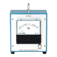
The Connection with MBD-D includes connection with K-thermocouple cable. Connect the
cable between the connector on the K thermocouple and the K Thermo connector on the MBD-D.
The procedure is shown in
Figure 4-2.
(*2) MBS-MBD connection cable (5m)
(*2)The dotted lines are to be wired by customers.
(*3) The length of our optional MBD - MBS connection cable is maximum 20meters.
Figure 4-2 MBD-D and MBS Wiring
AWG #24, or 0.3mm
2
max.
A
B
C
A
B
A
B
A
B
C
D
ANALOG
OUT
A
B
C
A
B
MBD-D
ANALOG IN
Shielded Twisted Cable
DIGITAL IN
[Customer’s Control Board]
C
C
u
u
s
s
t
t
o
o
m
m
e
e
r
r
’
’
s
s
S
S
y
y
s
s
t
t
e
e
m
m
< 20K
> 280K
(*3)
(*3)
P
P
o
o
w
w
e
e
r
r
C
C
a
a
b
b
l
l
e
e
(Signal Cable)
K thermocouple
OUT
+
-
K Thermo
Cable
Shielded Twisted Cable
When routing cables;
In order to prevent mutual interference during operation, signal lines, control lines, and AC
power lines should be placed in separate conduits. Especially, do not route MBS analog
lines in ways as to place together with AC power lines or control lines of other equipments
in a same conduit, or to bundle them together. It may cause interference to MBS-C
operation.
In case that separated conduits are not possible, keep enough distance between the lines
(300mm or more) to avoid the interference.