Maintenance
12 221.100.002-00 03/2021
www.uni-geraete.com
13 Maintenance
Danger to life due to improperly maintained valves!
If the valves are maintained at intervals that are too long or by untrained personnel, this can lead to life-
threatening injuries from escaping media.
• Observe the maintenance intervals specified in the maintenance schedule.
• Maintenance should only be carried out by personnel trained by the manufacturer.
For dates and prices of manufacturer training courses, please contact the sales department (see cover sheet).
13.1 Maintenance intervals
Solenoid valves must be checked at regular intervals for function and internal leak tightness.
The intervals for regular checks must be determined by the operator according to the operating conditions.
Uni-Geräte prescribes the following maintenance intervals:
• Annually:
External visual inspection, as well as function test and internal and external leakage test (See “External
visual inspection” on page 12).
• Every five years (only for valves for which spare parts kits are available):
Internal visual inspection with replacement of all sealing elements. Then perform a functional test and an
internal and external leakage test (See “Internal visual inspection with replacement of all sealing ele-
ments” on page 12).
• Every ten years or at the latest after the following number of switching cycles:
Complete revision of the valve by the manufacturer (See “Maintenance at the manufacturer” on page 13).
13.2 Maintenance at the plant operator
External visual inspection
1. Check the valve and the paint for obvious damage and corrosion.
2. Check the valve for internal leaks.
3. Check the valve for external leaks.
4. Subject the valve to a functional test.
5. In the event of damage or reduced function: Replace the complete valve. Contact the manufacturer.
Internal visual inspection with replacement of all sealing elements
An internal visual inspection is only required for models for which spare parts kits are available.
1. Remove the valve from the system (See “Disassembly” on page 15).
2. Disassemble the valve:
• Flange version 4/10-EVSA...; 16-EVSA 30N(H)..: (Page 14)
• Flange version 16/25-EVSA: (Page 14)
• Threaded version 4/10-EVSA 10 – 20 (1” – 2”): (Page 14)
3. Check the following items (see Fig. 1 – Fig. 7):
• Damage to the valve seat (100)
• Damage to the valve disc seal (400)
• Damage due to corrosion
• Wear on the guide rings (206)
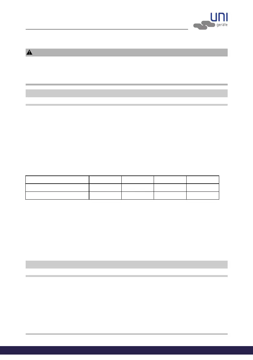
Operating temperature DN ≤ 25 ≤ DN 80 ≤ DN 150 > DN 150
≤ 25°C 150,000 75,000 25,000 20,000
> 25°C 50,000 25,000 25,000 5,000