EasyManua.ls Logo

UNI-T UT33D User Manual

UNI-T UT33D
42 pages
To Next Page IconTo Next Page
To Previous Page IconTo Previous Page
Page #7 background image
l Before using the Meter inspect the case. Do not use the Meter if it is
damaged or the case (or part of the case) is removed. Look for cracks or
missing plastic. Pay attention to the insulation around the connectors.
l Inspect the test leads for damaged insulation or exposed metal. Check
the test leads for continuity. Replace damaged test leads with identical
model number or electrical specifications before using the Meter.
l Do not apply more than the rated voltage, as marked on the Meter, between
the terminals or between any terminal and grounding.
l The rotary switch should be placed in the right position and no any
changeover of range shall be made during measurement is conducted to
Warning
To avoid possible electric shock or personal injury, and to avoid possible
damage to the Meter or to the equipment under test, adhere to the following
rules:
Rules For Safe Operation (1)
7
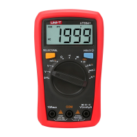
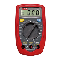
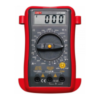
Model UT33B/C/D: OPERATING MANUAL
Question and Answer IconNeed help?

Do you have a question about the UNI-T UT33D and is the answer not in the manual?

UNI-T UT33D Specifications

General IconGeneral
Diode testYes
Product typeDigital multimeter
AC voltage range200 - 500 V
DC current range0.02 - 10 A
DC voltage range0.2 - 500 V
Basic accuracy (DC current)±(1%+2)
Basic accuracy (DC voltage)±(0.5%+2)
Basic accuracy (resistance)±(0.8%+2)
Dimensions (WxDxH)73.5 x 35 x 130 mm
Battery voltage9 V
Weight and Dimensions IconWeight and Dimensions
Weight156 g

Summary

Overview

Unpacking Inspection

Safety and Safe Operation

Safety Information

This Meter complies with standards IEC61010, including pollution degree 2 and overvoltage categories CAT I 600V, CAT II 300V.

Rules For Safe Operation

Adhere to rules to avoid electric shock, personal injury, or damage to the Meter or equipment under test.

Device Identification

International Electrical Symbols

Explanation of international electrical symbols used on the Meter and within the operating manual.

The Meter Structure

Diagram and list identifying the components of the Meter, such as LCD Display, HOLD Button, Rotary Switch, and Input Terminals.

Functional Buttons

Measurement Operations

DC Voltage Measurement

Procedure for measuring DC voltage, including connecting test leads and setting the rotary switch to the V range.

AC Voltage Measurement

Procedure for measuring AC voltage, including connecting test leads and setting the rotary switch to the V range.

DC Current Measurement

Warning and procedure for measuring DC current, emphasizing proper terminals and avoiding parallel connection.

Measuring Resistance

Warning and procedure for measuring resistance, including disconnecting power and discharging capacitors.

Diodes and Continuity Measurement

Warning and procedure for testing diodes, including checking junction voltage drop.

Model UT33C: Temperature Measurement

Warning and procedure for measuring temperature using Model UT33C, including connecting the temperature probe.

Model UT33B: Battery Test

Warning and procedure for testing batteries using Model UT33B, including connecting leads and checking polarity.

Model UT33D: Square Wave Output

Warning and procedure for measuring square wave output using Model UT33D, including setting the rotary switch.

General Specifications

Accuracy Specifications

DC Voltage

Accuracy specifications for DC Voltage measurement across different ranges and models, including overload protection.

AC Voltage

Accuracy specifications for AC Voltage measurement across different ranges and models, including input impedance and frequency response.

DC Current

Accuracy specifications for DC Current measurement across different ranges and models, including overload protection and continuous measurement limits.

Resistance

Accuracy specifications for Resistance measurement across different ranges and models, including overload protection.

Diodes and Continuity Measurement

Accuracy specifications for Diode and Continuity Measurement, including remarks on voltage drop and buzzer operation.

Model UT33C: Temperature

Accuracy specifications for Temperature measurement on Model UT33C, including ranges and overload protection.

Model UT33B: Battery Test

Specifications for Battery Test on Model UT33B, including range, resolution, and internal resistance.

Model UT33D: Square Wave Output

Specifications for Square Wave Output on Model UT33D, including illustration and remarks on overload protection.

Maintenance

General Service

Guidance on general service, including cleaning the case and terminals, and storing the meter when not in use.

Replacing the Battery

Warning and procedure for replacing the battery, emphasizing replacement upon seeing the battery indicator.

Replacing the Fuses

Warning and procedure for replacing the meter's fuses, emphasizing the use of specified fuses only.

Copyright and Contact Information

Related product manuals