9 10
6.1.2.6 Ethernet Port Detected
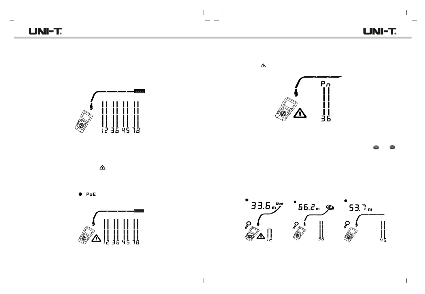
Figure 6.7 shows that the tester detects Ethernet port.
The tester cannot measure the length if the port does not produce reflections. Length
may fluctuate or be obviously too high if the port’ s impedance fluctuates or varies from
the cable’s impedance. When in doubt, disconnect the cable from the port to get an
accurate lenth measurement.
6.1.2.7 POE Switch Detected
Figure 6.8 shows the tester detects the POE switch.
In testing mode, the tester can identify if the device connected by measured cable is POE
switch or not, and displays “POE” and “ ”.
In testing mode, the tester cannot identify IEEE 802.3af, IEEE 802.3at and IEEE 802.3bt.
To know about the power supply standards of POE switch, please perform test on the
switch under POE mode. (See “POE Mode”)
Figure 6.7 Ethernet Port Detected
Figure 6.8 POE Switch Detected
6.1.2.8 Voltage Detection
Figure 6.9 shows that the tester detects cable voltage.
If the measured cable is live and its voltage is greater than or equal to 10V, the tester
will show “ ” and “Pn” (P: positive; n: negative).
6.1.2.9 View Details for a Wire Pair
Figure 6.10 shows that the tester displays details for each wire pair. Use “ ”and “ ”
to move through the screens. In this mode, the tester continuously tests only the wire
pair you are viewing.
A: Short on pair 1, 2 at 33.6m. Note: On the results details screens, shorts are shown only
when they are between wires in a pair. When there is a short, the far-end adapter and
the mapping of the unshorted wires are not shown.
B: Pair 3, 6 is 66.2m long and is terminated with wiremap adapter.
C: Open on pair 4, 6 at 53.7m. The open could be on one or both wires.
Figure 6.9 Cable Voltage Detection
Figure 6.10 Details for a Wire Pair
A B C
UT685B/UT685B KITUT685B/UT685B KIT