11 12
6.1.2.10 Connecting to Telephone Networks Wired in Star Topologies
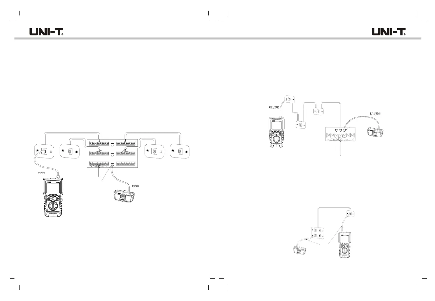
Telephone cables wired in a star topology (Figure 6.11) are connected together at a bridge
gap at the distribution center. The bridge gap connects each wire to all other wires of the
same number. The tester detects bridge taps and measures the distance to the bridge gap.
To measure the length of each cable connected to the bridge gap, connect the wiremap
adapter to the bridge gap and the tester to the wall outlet.
The tester cannot measure length past the bridge gap because reflections from the bridge
gap connection interfere with measurement. If you connect the tester to the bridge gap,
the tester measures the length only to the bridge gap, which is only the patch cord length.
(Do not use multiple far-end adapters in star or bus topologies. Doing so causes incorrect
wiremap results.)
Figure 6.11 Connecting to Telephone Networks Wired in Star Topologies
Wall
outlet
Distribution center
Wall
outlet
Common connection to bridge gap
Far-end adapter
6.1.2.11 Connecting to Telephone Networks in Bus Topologies
Telephone cables wired in a bust topology (Figure 6.12) connect the wall outlets in series.
In this topology, you measure the length from the last outlet to the wiremap adapter.
If you connect to an outlet in the middle of the series, the tester reports a bridge gap. The
length report is the length to the outlet, which is the patch cord length. The tester cannot
measure length past the outlet because reflections from the cables on either side interfere
with measurements.
Wall
outlet
Distribution center
Far-end adapter
Connection to bus
Figure 6.12 Connecting to Telephone Networks in Bus Topologies
6.2 Testing Coaxial Cabling
6.2.1 Coaxial Cabling Testing
(1) Turn on the tester, and set the knob to “TEST”, then press “PORT” to switch to coaxial
test mode.
(2) Connect the tester and wiremap adapter to the cabling.
(3) For cabling not terminated with and F-connector, use an adapter or hybrid patch cord
to connect to the cabling. The test runs continuously until you change modes or turn
the tester off.
Wall outlet
Connection to service
Far-end adapter
Coaxial cables
Figure 6.13 Connecting to Coaxial Cabling
UT685B/UT685B KITUT685B/UT685B KIT