13 14
6.2.2 Typical Testing Results
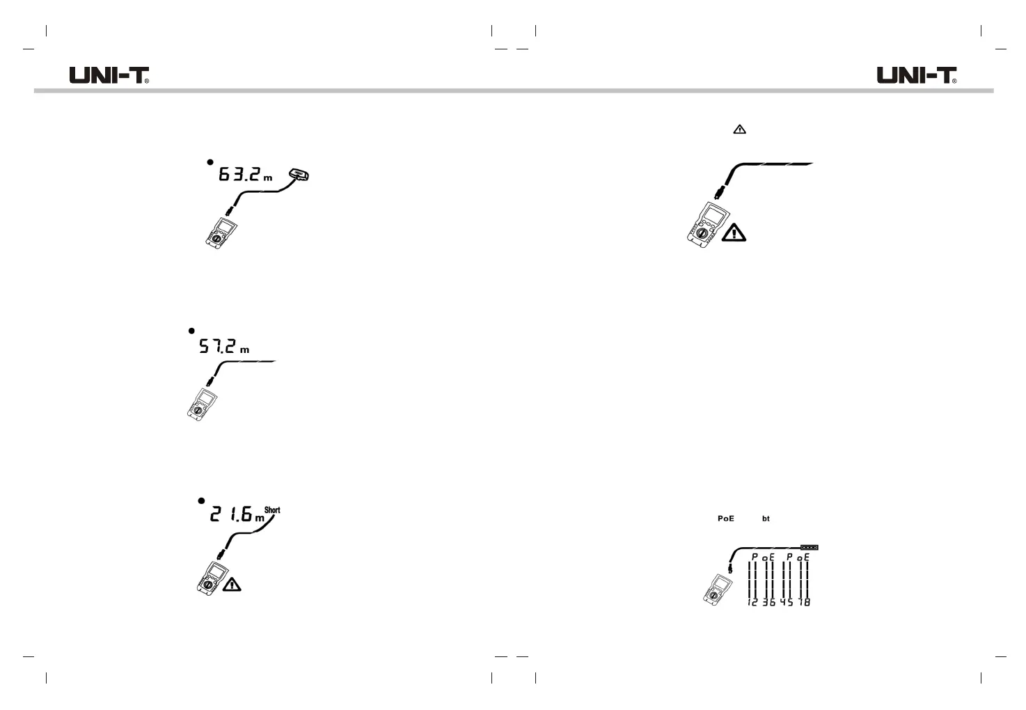
6.2.2.1 Results for a Good Coaxial Cable
Figure 6.14 shows a good coaxial cable 63.2m and terminated with far-end adapter
.
Figure 6.14 Coaxial Results
6.2.2.2 Open on Coaxial Cabling
Figure 6.15 shows an open 57.2m from the tester.
Figure 6.15 Open on Coaxial Cabling
6.2.2.3 Short on Coaxial Cabling
Figure 6.16 shows a short 21.6m from the tester.
Figure 6.16 Short on Coaxial Cabling
6.2.2.4 Voltage on Coaxial Cabling
Figure 6.17 shows that the symbol “ ” appears if the coaxial cable is live and its voltage
is greater than or equal to 10V.
Figure 6.17 Voltage on Coaxial Cabling
VII. POE Mode
As shown in figure 7.1, turn on the tester, and set the knob to POE mode, then the symbol
“POE” appears on the display. The tester shows and identifies af/at/bt., and is connected
to power supply device using IEEE 802.3bt standard. In POE mode, the tester detects
POE on pairs 1,2-3,6 and 4,5-7,8. The tester may activate a POE source and will not be
damaged by POE.
“IEEE 802.3af: CSMA/CD Access Method and Physical Layer Specifications - Data
Terminal Equipment (DTE) Power via the Media Dependent Interface (MDI)”
“IEEE 802.3at: CSMA/CD Access Method and Physical Layer Specifications - Data
Terminal Equipment (DTE) Power via the Media Dependent Interface (MDI) Enhancements”
“IEEE 802.3bt: Physical Layer and Management Parameters for Power over Ethernet over
4 pairs”
Figure 7.1 POE Display
If POE is detected, “POE” appears above the powered pairs. The “POE” may blink as
the POE source turns the power on and off.
The tester can detect if the connected device is powered by POE, and can identify
three different POE standards including IEEE 802.3af, IEEE 802.3at, IEEE 802.3bt.
If a non-standard POE device is connected, the tester is not able to detect whether
the connected device is POE powered or not, and needs to switch to TEST mode to
detect whether the device is powered or not.
UT685B/UT685B KITUT685B/UT685B KIT