Do you have a question about the UNI-T UTD2072CL and is the answer not in the manual?
Inspect the instrument for damages and check accessories after purchase.
Perform a fast function check to verify the oscilloscope is operating normally.
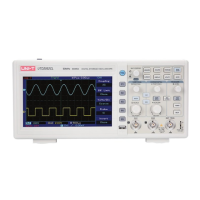
Description of the front and rear panels of the oscilloscope, including controls and interfaces.
Explanation of the display screen elements, status bar, and soft button menus.
How the DSO automatically adjusts vertical scale, time base, and trigger for optimal waveform display.
Overview of the vertical control area, including position and scale adjustments.
Overview of the horizontal control area, including time base scale and position adjustments.
Overview of the trigger control area, including level adjustment and trigger menu.
Configuring the coupling mode (AC, DC, GND) to filter or pass signal components.
Setting the bandwidth limit (e.g., 20MHz or Full BW) to filter high-frequency components.
Setting the probe attenuation coefficient (e.g., 10x) in the channel menu for accurate readings.
Adjusting the vertical scale (Volts/Div) for optimal waveform display resolution.
Inverting the displayed waveform by 180 degrees using the Invert function.
Setting the display unit for channels to Volts (V) or Amps (A).
Performing mathematical operations (+, -, ×, ÷) on waveforms from different channels.
Converting time-domain signals to frequency-domain using Fast Fourier Transform (FFT).
Filtering signal frequencies using digital filter settings like low pass or band pass.
Controlling the horizontal time base scale and waveform position on the screen.
Definitions of key terms like YT Mode, XY Mode, Scan Mode, and SEC/DIV.
Enlarging waveforms for detailed viewing using window extension and time base adjustment.
Using XY Mode (Lissajous figures) to measure phase difference between two signals.
Overview of trigger level, set to zero, and trigger menu controls for stable waveform capture.
Triggering the oscilloscope based on the rising or falling edge of a signal.
Triggering the oscilloscope based on the width of a specific pulse.
Triggering the oscilloscope based on the rising or descending slope of a signal.
Triggering on fields or lines of NTSC or PAL standard video signals.
Triggering between two vertical channels for signals with different frequencies.
Setting holdoff time to prevent re-triggering for complex waveforms like pulse strings.
Definitions of trigger source, trigger mode (auto, normal, single), and trigger coupling.
Setting acquisition modes (sampling, peak value, average), averages, and fast acquisition.
Options for display type, persistence, menu timeouts, brightness, and grid styles.
Selecting sources, parameter display (all/custom), indication, and measurement statistics.
Diagram and definitions of voltage parameters like Vmax, Vmin, Pk-Pk, and Amplitude.
Diagram and definitions of timing parameters like Period, RiseTime, FallTime, and Pulse Width.
Definitions of other parameters including duty, overshoot, preshoot, area, and phase.
Menu for setting cursor measurement type (time/voltage), mode, unit, and source.
How to move and use cursors for measuring voltage differences and time intervals.
Setting up storage type (setup, reference, data file), location, saving, and loading settings.
Storing and loading reference waveforms from internal memory or USB.
Storing and loading bitmap images of the screen via USB.
Capturing the current screen to USB in BMP format using the PrtSc button.
System setup, language selection, LAN setup, self-calibration, and system information.
Detecting if the input signal is within a specified template scope (PASS/FAIL).
Recording waveforms frame by frame using the built-in recorder function.
Configuring parameters for automatic waveform setting to optimize display.
Automatic adjustment of time-scale, Volt/Divs, and trigger for optimal waveform display.
Switching the oscilloscope between running (collecting data) and stopping states.
Accessing help information for specific keys and functions.
Updating the DSO firmware via USB by following specific steps.
Measuring signal frequency and peak-to-peak value using auto measurement.
Observing signal delay and waveform changes through a circuit using dual channels.
Acquiring non-cyclical signals like pulses and glitches using trigger setup.
Filtering or reducing random noise in measured signals using trigger coupling and sampling modes.
Measuring time and voltage of a waveform using the oscilloscope's cursors.
Explanation of common system prompts, such as 'Adjustment at Ultimate Limit'.
Common troubleshooting steps for issues like no waveform display or no trigger.
List of standard and optional accessories included with the oscilloscope.
Guidelines for general maintenance and cleaning of the instrument and probes.
Information regarding the product warranty terms, duration, and service.
| Bandwidth | 70 MHz |
|---|---|
| Sample Rate | 1 GSa/s |
| Channels | 2 |
| Display | 7 inch TFT LCD |
| Rise Time | ≤ 5 ns |
| Display Resolution | 800 x 480 pixels |
| Trigger Type | Edge, Pulse |
| Interfaces | USB |
| Power | 100-240 VAC, 50/60 Hz |
| Vertical Resolution | 8 bit |
| Power Supply | 100-240 VAC, 50/60 Hz |