Do you have a question about the UNI-T UTD2000CEX+ Series and is the answer not in the manual?
Information regarding copyright and declaration of the product.
Specifications for power cord sets required for different regions.
Information on how RF magnetic fields affect the product's operation.
Defines warning, danger, and note terms used in the manual.
Explains various safety symbols and their meanings.
Lists the different models within the UTD2000 series.
Steps for inspecting the instrument after purchase.
Procedures for verifying the instrument's normal operation.
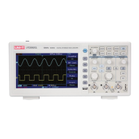
Description of the front and rear panels of the oscilloscope.
Description of the oscilloscope's display interface and elements.
How to use the automatic setting function for waveform display.
Overview of the vertical control area and its functions.
How to set the coupling mode (AC, DC, GND) for input channels.
How to set the bandwidth limit for input channels.
How to configure the probe attenuation coefficient in the channel menu.
How to adjust the vertical scale (Volts/Div) for coarse and fine settings.
How to invert the displayed waveform.
How to set the display unit (V or A) for the channel.
Performing mathematical operations on waveforms (add, subtract, multiply, divide).
Performing Fast Fourier Transform for spectral analysis.
Applying digital filters to modify signal frequency characteristics.
Controls for adjusting horizontal time base and position.
Defines terms like YT Mode, XY Mode, Scan Mode, and SEC/DIV.
Using window extension to enlarge waveform details.
Using XY Mode (Lissajous Figure Mode) to measure phase difference.
Overview of trigger control elements like LEVEL, SET TO ZERO, and TRIG MENU.
How to set up edge triggers based on signal rise or fall.
Setting triggers based on the pulse width of the signal.
Triggering based on the slope of the signal's rising or falling edge.
Setting up triggers for video signals (NTSC/PAL, field/line).
Triggering using signals from two channels, useful for different frequencies.
Setting holdoff time to prevent re-triggering during complex waveforms.
Definitions of trigger source, trigger mode, trigger coupling, and pretrigger.
Settings for data acquisition modes like Peak Value, High Resolution, Average.
Settings for display types, persistence, and screen protection.
Settings for waveform, grid, and backlight brightness.
Menu for selecting automatic measurement parameters.
Definitions and diagrams for voltage parameters (Max, Min, Pk-Pk, etc.).
Definitions and diagrams for timing parameters (Period, Rise Time, Fall Time, etc.).
Definitions for other measurement parameters like duty, area, and phase.
Menu for setting up cursor measurement type, mode, and source.
How to use cursors for measuring voltage and time on the waveform.
How to set storage type, location, save, and load settings.
How to store and load reference waveforms and data files.
How to store and load screen bitmaps (BMP format).
How to take a screenshot of the current screen.
System setup options including self-calibration and information.
Select interface language for the oscilloscope.
Performing Pass/Fail tests on input signals against a template.
Recording and replaying waveform frames.
Configuring the AUTO setting behavior for channels, sampling, and trigger.
Configure network settings for the oscilloscope.
Execute the self-calibration function for the instrument.
How the AUTO setting works and its applicable conditions.
Function of the RUN/STOP button for controlling data acquisition.
Accessing the help menu for information on keys.
Steps for upgrading the oscilloscope firmware via USB.
Measuring frequency and peak-to-peak value of a simple signal.
Measuring signal delay and waveform changes through a circuit.
Acquiring non-cyclical signals like pulses and glitches.
Reducing random noise in signals using trigger coupling and sampling modes.
Using cursors to measure time and voltage of a waveform.
Explains various system prompts displayed by the oscilloscope.
Provides solutions for common issues like no waveform, voltage problems, and no trigger.
Lists basic specifications like model, bandwidth, rise time, and sampling rates.
Specifications related to the acquisition system, such as average settings.
Specifications for input channels, including coupling, impedance, and voltage limits.
Specifications for the horizontal system, including time-base scale and interpolation.
Specifications for vertical system parameters like channels, A/D, deflection factor, and accuracy.
Specifications for trigger system parameters like sensitivity, range, and level accuracy.
Details on manual and automatic measurements, including cursor and parameter lists.
Specifications for math operations, window functions, and digital filtering.
Specifications for storage types, reference waveforms, data files, and bitmaps.
Specifications for the display, including type, resolution, color, and language.
Specifications for interface functions like USB, EXT Trig, and Pass/Fail.
Environmental specifications like intended use, temperature, humidity, and altitude.
Mechanical specifications including size and weight.
Lists standard and optional accessories for the UTD2000 series.
Guidelines for general maintenance and cleaning of the instrument and probe.
Details of the product warranty provided by UNI-T.
Information on how to contact UNI-T for product support and service.
| Channels | 2 |
|---|---|
| Power Supply | 100-240V AC, 50/60Hz |
| Type | Digital Oscilloscope |
| Bandwidth | 200 MHz |
| Sample Rate | 1 GS/s |
| Display | 7 inch LCD |
| Display Resolution | 800 x 480 pixels |
| Vertical Scale | 2 mV/div to 10 V/div |
| Trigger Types | Edge, Pulse, Video, Slope, Alternative |
| Interfaces | USB Host, USB Device |