22
Installation info
fig. 19
fig. 20
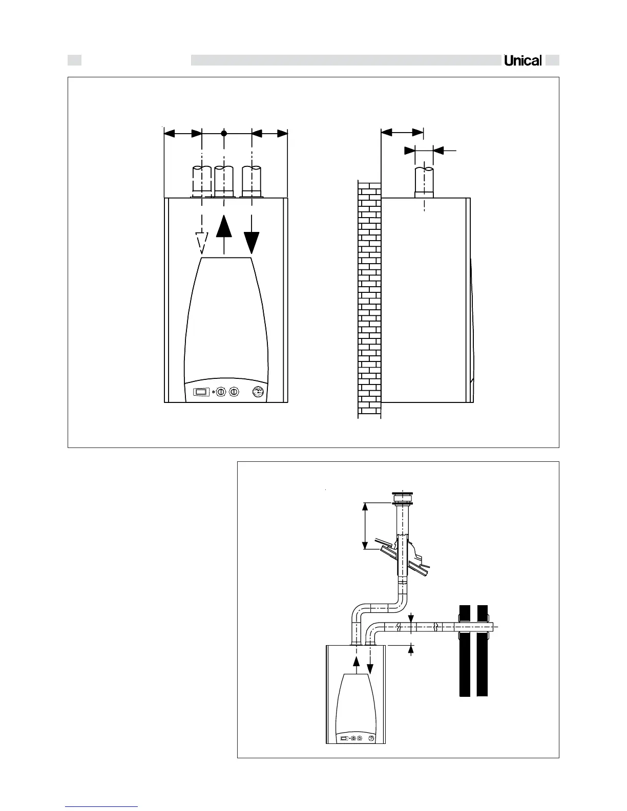
DIMENSIONS FOR CONNECTION THE AIR INTAKE AND THE FLUE GAS DISCHARGE WITH DUAL DUCTS
_
>
500
Hmin. = 150 mm
CONFIGURATIONS FOR SEPARATE
PIPES (SUCTION AND OUTLET) Ø 80
Example N.1
Primary air suction from perimeter wall and
flue gas discharge on roof.
Maximum allowable pressure loss:
50 Pa
87
120 152
Ø 80
123
90
Example N.1
 Loading...