23
Installation info
fig. 22
fig. 21
135
45
C
2
1
250 min.
Example of check using wide radius
bends:
- 17 mt duct Ø 80 x 2 = 34 Pa
- 2x90° Ø 80 long radius bends 2x4 = 8 Pa
- horizontal Ø 80 air inlet terminal = 3 Pa
- horizontal Ø 80 terminal = 5 Pa
Tot. pressure loss = 50 Pa
1
2
A
Air
inlet
1
Smoke
outlet
B
2
Example N.2
CALCULATION OF PRESSURE LOSSES
FOR DISCHARGE AND SUCTION DUCTS
Bear in mind the following parameters when
calculating pressure losses:
- for each metre of duct with Ø 80 (both
suction and discharge) the pressure loss
is 2 Pa;
- for each 90° Ø 80 (R=D) bend with long
radius, the pressure loss is 4 Pa;
- for each 90° Ø 80 (R=½ D) bend with
short radius, the pressure loss is 14 Pa
- for the Ø 80 L = 0.5 m horizontal air inlet
terminal, the pressure loss is 3 Pa;
- for the Ø 80 L = 0.6 m horizontal
discharge end section, the pressure loss
is 5 Pa;
NB: These values refer to dis-
charges through original UNI-
CAL non-flexible and smooth
ducts.
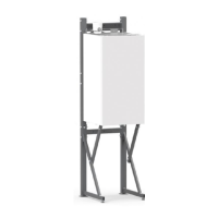
Example N.2
Primary air suction from perimeter wall and
flue gas discharge from the same outside pe-
rimeter wall.
It is not allowed to position the 2 termi-
nals in opposite walls,
Maximum allowable pressure loss:
50 Pa
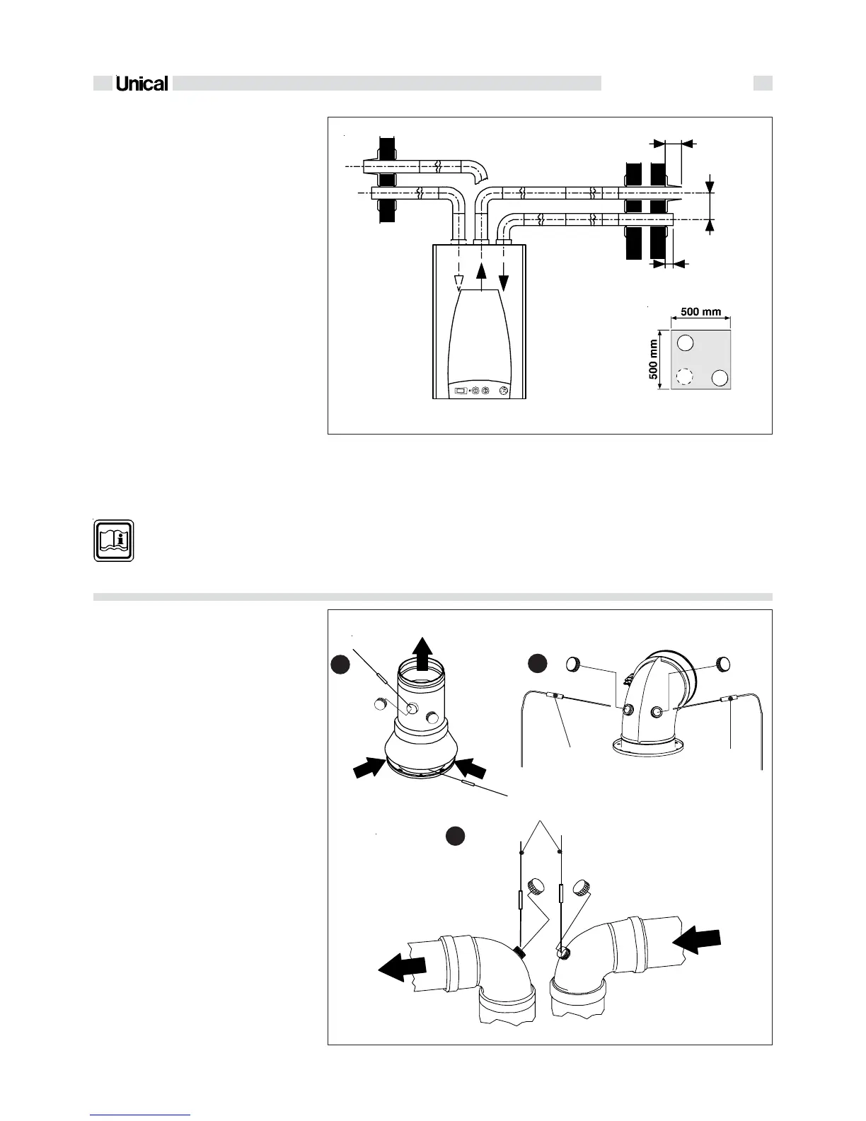
2.2.11- MEASUREMENTS OF
COMBUSTION EFFICIENCY
Ducts Ø 80 type B22 (C)
Coaxial ducts (A)
Dual ducts Ø 80 (B)
To determine combustion efficiency the fol-
lowing measurements must be made:
- the combustion air temperature measured
in hole 2 (see fig. 22).
- the flue gas temperature and CO
2
% mea-
sured in hole 1 (see fig. 22).
Make these measurements with the boi-
ler running in a steady state condition.
Air
inlet
Smoke
outlet
Analyser
probe
Analyser
probe
Analyser
probe
Analyser
probe
 Loading...