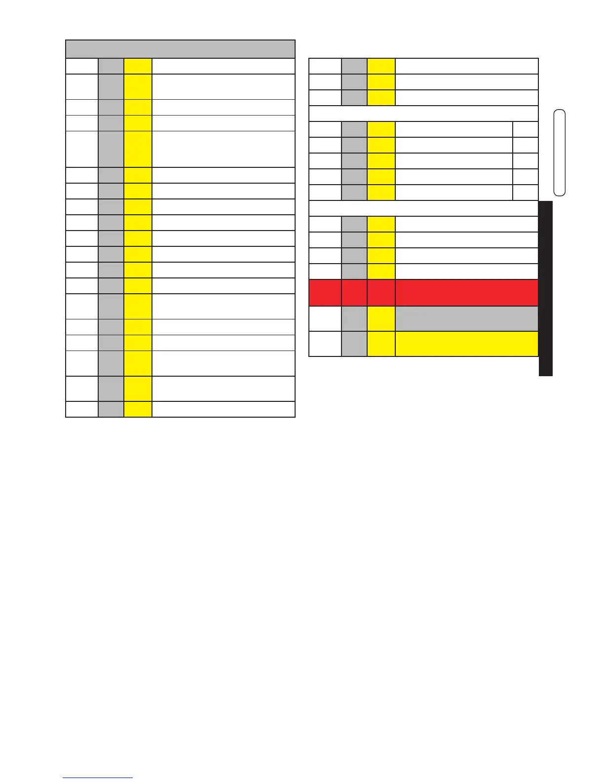
KEY
N° C.E. S.E. Description
1 db SS Domestic hot water temperature
sensor
2 FLS Flow switch with cold water lter
3 VG Gas valve
4 Fd E.
ACC
/RIL
Ignition/detection electrode
5 Burner
8 Expansion vessel
10 HL TL Safety thermostat
11 Hb SR Heating temperature sensor
12 Ht P Pump
13 Lp SPI Water deciency pressure switch
16 Diverter valve
17 Plate heat exchanger
18 FL
FH
VM
Fan
20 Safety valve
22 rb SRR Return temperature sensor
23 tf TLC Flue gas collector safety ther-
mostat
24 Aluminium Heat Exchanger/Ca-
pacitor
25 Vent valve
26 Condensation drain trap
35 Service panel
36 Manometer
C Domestic hot water outlet G ½
G Gas inlet G ¾
F Cold water inlet G ½
M Heating system ow G ¾
R Heating system return G ¾
Rc Filling valve
Sc Boiler drain
Svs Safety valve drain
Scond
Condensation drain
Ufp Smoke rear output optional
not avaible at moment on 24 kW.
C.E. = ERROR CODES see
par. 4.6
S.E. = WIRING DIAGRAM
KEY see par. 4.5

 Loading...