40
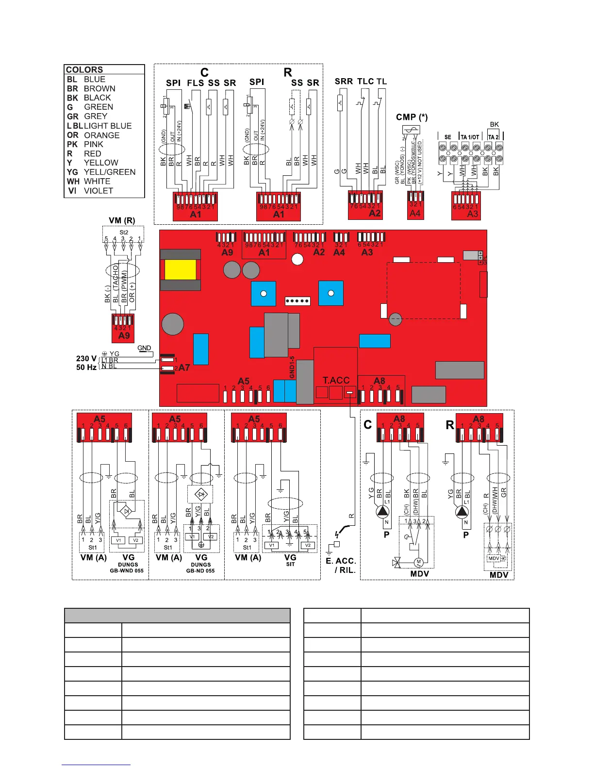
4.5 - WIRING DIAGRAM
Practical connection board
KEY
A1.....A9 Services connectors
CMP Modulating pump control
E.ACC./RIL Waterdeciencysafetypressureswitch
FLS Ignition/detection electrode
MVD Domestichotwaterrequestowswitch
P Pump
SPI Pressure Sensor System
SR Flowheatingsensor
SRR Returnheatingsensor
SS
Domestichotwaterprobe(Pred.forRmodels)
TL Limitthermostat
TLC Fluegascollectorlimitthermostat
VG Gas valve
VM Modulating fan
SE Externalprobeconnectionterminals
TA1 / OT Modulating TA connection terminals
TA2 On/off TA connection terminals

 Loading...