26
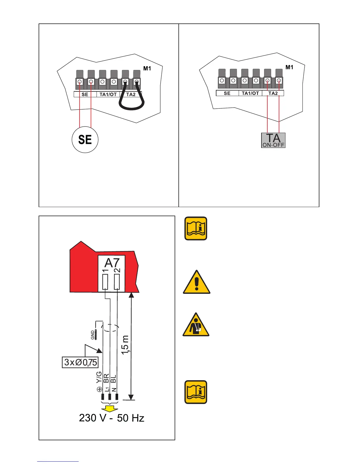
Electric power supply connection
SE = Outside sensor (*)
- Predisposed on the terminal block, terminals
SE
- Remove the jumper TA2.
Connect ON-OFF (2
a
ZONE alternate manage-
ment) between terminal TA 2
ON-OFF room thermostat (*)
CAVO/CABLE
PVC HT
H05V2V2-F
The boiler is equipped with a power
cable, boiler installation requires elec-
tric al connection to the mains power
supply. This connection must be made
up to standard, as required the regula-
tions in force.
Remember that a bipolar switch must
be installed on the boiler power line
with over 3 mm between contacts, easy
to access, making maintenance quick
and safe.
The power cable must be replaced
by technical personnel authorised by
UNICAL AG S.p.A., using original spare
parts only. Failure to comply with the
above can jeopardise the safety of the
appliance.
If necessary the shield of the sensor
cable, can be connected to the termi-
nal. (Ground connections - modulation
board).
See par. 4.4 positioning on the board
(*) Optional
NOTE!
For more information See Technical Info
from site indicated at pag. 2

 Loading...