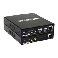
18
Configure the Transmitter Console
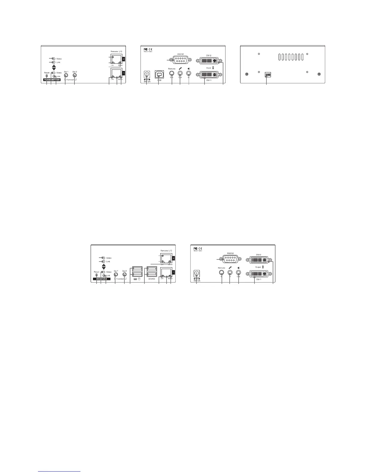
14 15 17 18 19 20 21
16
ON DIP
1 2 3 4
221 2 3 4 5 6 7 8
9
10
11
12
13
1. Connect one end of a CATx UTP cable to the port 1 (No.7) of Transmitter, and other end to the port of
Gigabit Ethernet Hub (not available on the box). Repeat this step to connect the second port (No.11) of
transmitter to the Hub.
2. Power up the unit by pugging the power adapter into power jack (No.14).
3. Connect USB port (Type B, No15) cable to PC USB port. The keyboard and mouse of the receiver may
not function if failing to connect here.
4. Connect to a IR emitter to the remote out jack (No.17).
5. Connect an audio cable to mic. connector of PC (No.18).
6. Connect an audio cable to speaker in jack of PC (No.19).
7. Connect the DVI cable between the Transmitter’s DVI port (No.20) and PC’s DVI port. Repeat this step
to connect the second DVI port (No.21).
8. Connect to the RS-232 port of PC (No.16).
Configure the Receiver Console
14 17 18 19 20 21
16
1 2 3 4 5 23 24 6 7 8
9
10
11
12
13
1. Connect USB keyboard and mouse to USB ports (No.23).
2. Connect devices to USB devices ports (No.24).
3. Connect one end of a CATx UTP cable to the port 1 (No.7) of Receiver, and other end to the port of
Gigabit Ethernet Hub (not available on the box). Repeat this step to connect the second port (No.11) of
transmitter to the Hub.
4. Connect the IR receiver to the remote in jack (No.17).
5. Connect a microphone to mic. in connector (No.18).
6. Connect a speaker to speaker out connector (No.19).
7. Connect the DVI cable between the Receiver’s DVI port (No.20) and monitor’s DVI port. Repeat this
step to connect the second DVI port (No.21).
8. Connect to a RS-232 device (No.16).
9. Power up the unit by plugging the power adapter into power jack (No.14).