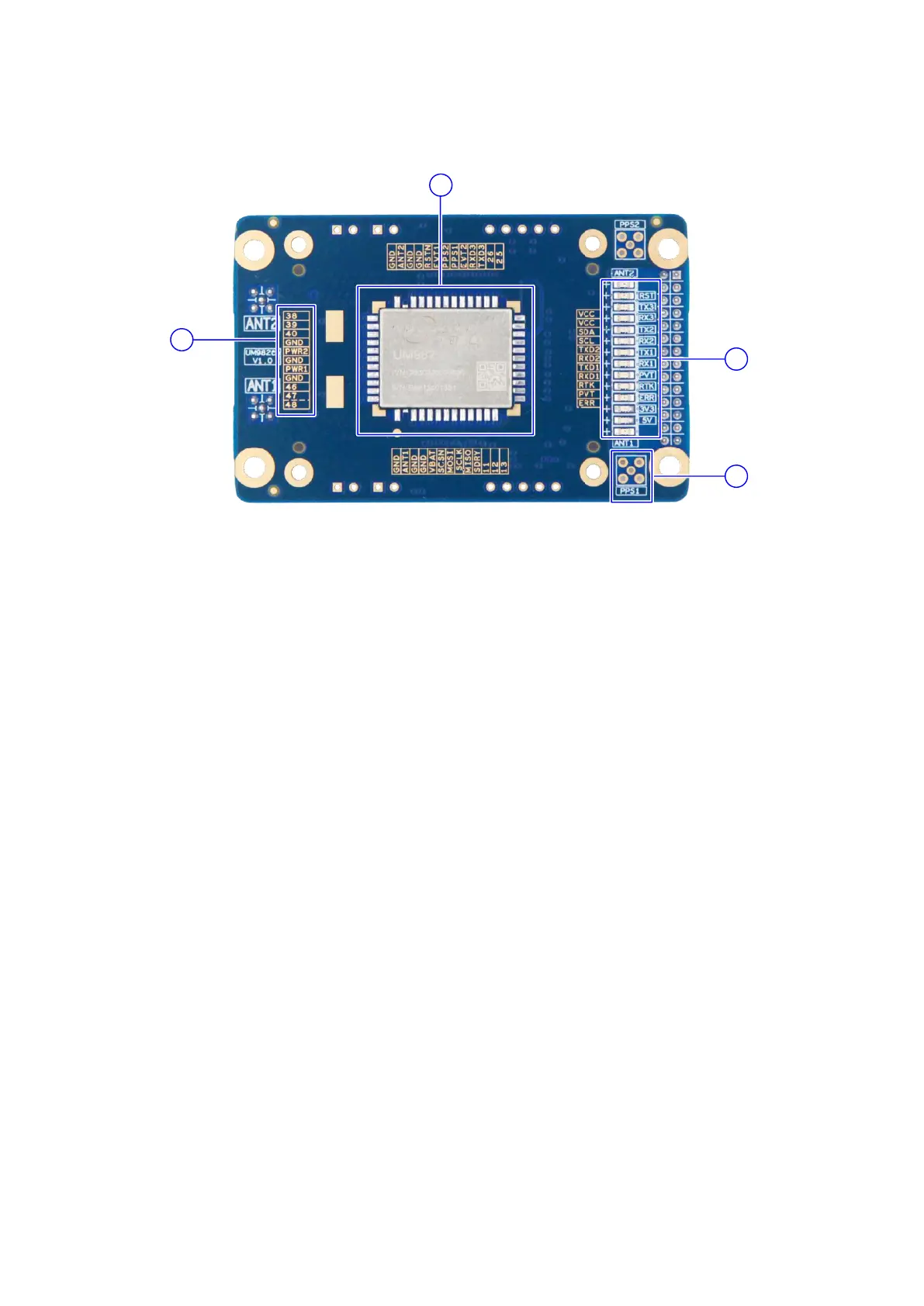
Figure 1-2 Top View of UM982eb
(1) Silkscreen: It marks the signals of the pins. The smaller holes around are used to
mount the UM982 socket. The printing adopts exposed copper to ensure the
flatness of the surface.
(2) UM982 module: The pin pads are designed long, which is convenient for soldering,
testing and debugging. For detailed packaging information, please refer to the
PCB document.
(3) PPS connector: To measure the PPS signal, solder an MMCX connector here.
(4) LED indicators: Indicating the status of the power supply, reset, antenna short
circuit, the positioning status and UART.