UM982-EB User Manual
10 Antenna circuit UC-08-M31 EN P1.0.3
V_BCKP.
4 Antenna circuit
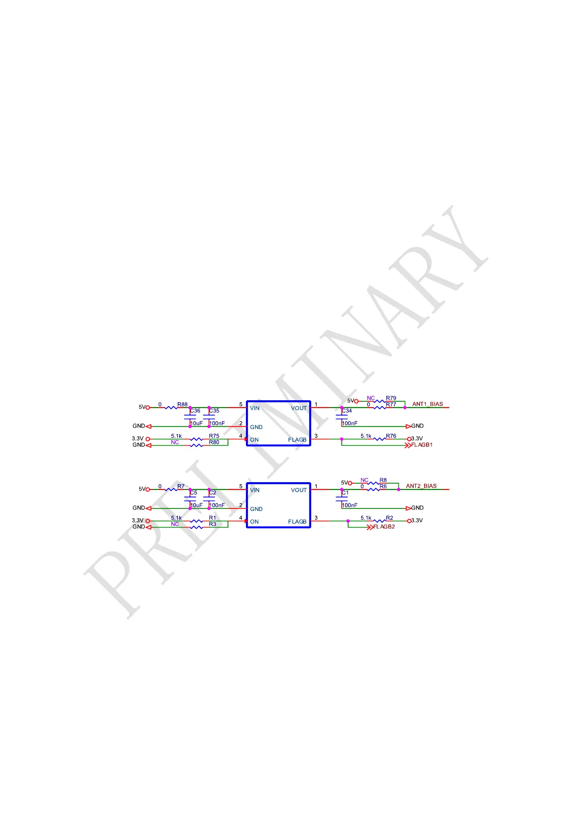
4.1 Antenna Short Protection Circuit
The antenna short protection circuit consists of a load management chip and peripheral
circuits.
The 5 V power source supplies the antenna after passing through the load management
chip.
When the current of the antenna circuit is greater than 100 mA, it will trigger short circuit
protection, and FLAGB will output low level signals.
Removing R88/R77 (or R7/R6) and soldering R79 (or R8), you can feed ANT1 (or ANT2)
bypassing the short protection circuit.