UC-08-M31 EN P1.0.3 UM982 Peripheral Design 13
Table 5-1 Description of the LED Status
Light on when the power is normal
Light on when pressing the reset button
Light on when antenna is shorted
Light on when position is fixed
Light on when RTK is fixed
Light on when failing self-test
Blinking when UART is working
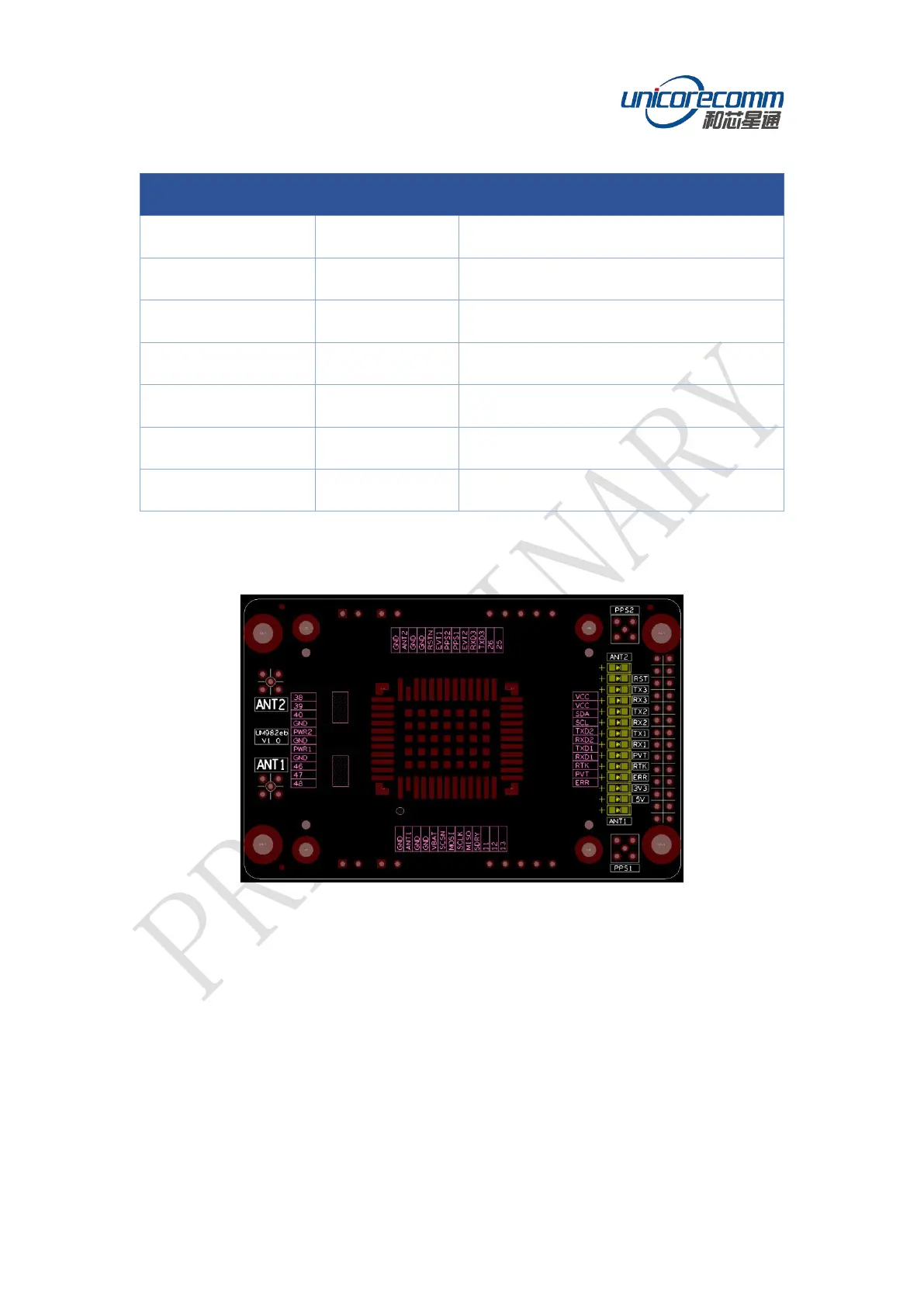
The silkscreen markings on the right of the LED indicators identify the corresponding
function, as shown in the figure below:
Figure 5-2 Markings on the Right of the LED Indicators
6 UM982 Peripheral Design
TVS anti-surge protection is added at the input of the UM982 module. ESD protection is
added at all pins.
Use large and small VCC filter capacitors together, with a total capacitance greater than
30 uF.
Add series resistors at the IO pins for the convenience of debugging.