UM982-EB User Manual
14 UM982 Peripheral Design UC-08-M31 EN P1.0.3
VCCIN powers the UM982 module only. R27 is a large-size resistor (with high rated power)
to ensure the current capability. In the figure below, a 0805 resistor is used.
Removing R27, connecting a power supply wire at TP1 and a ground wire at TP3 (as
shown in Figure 7-1), you can use an external power to supply the module. This method
can be used to measure the input voltage and current of UM982.
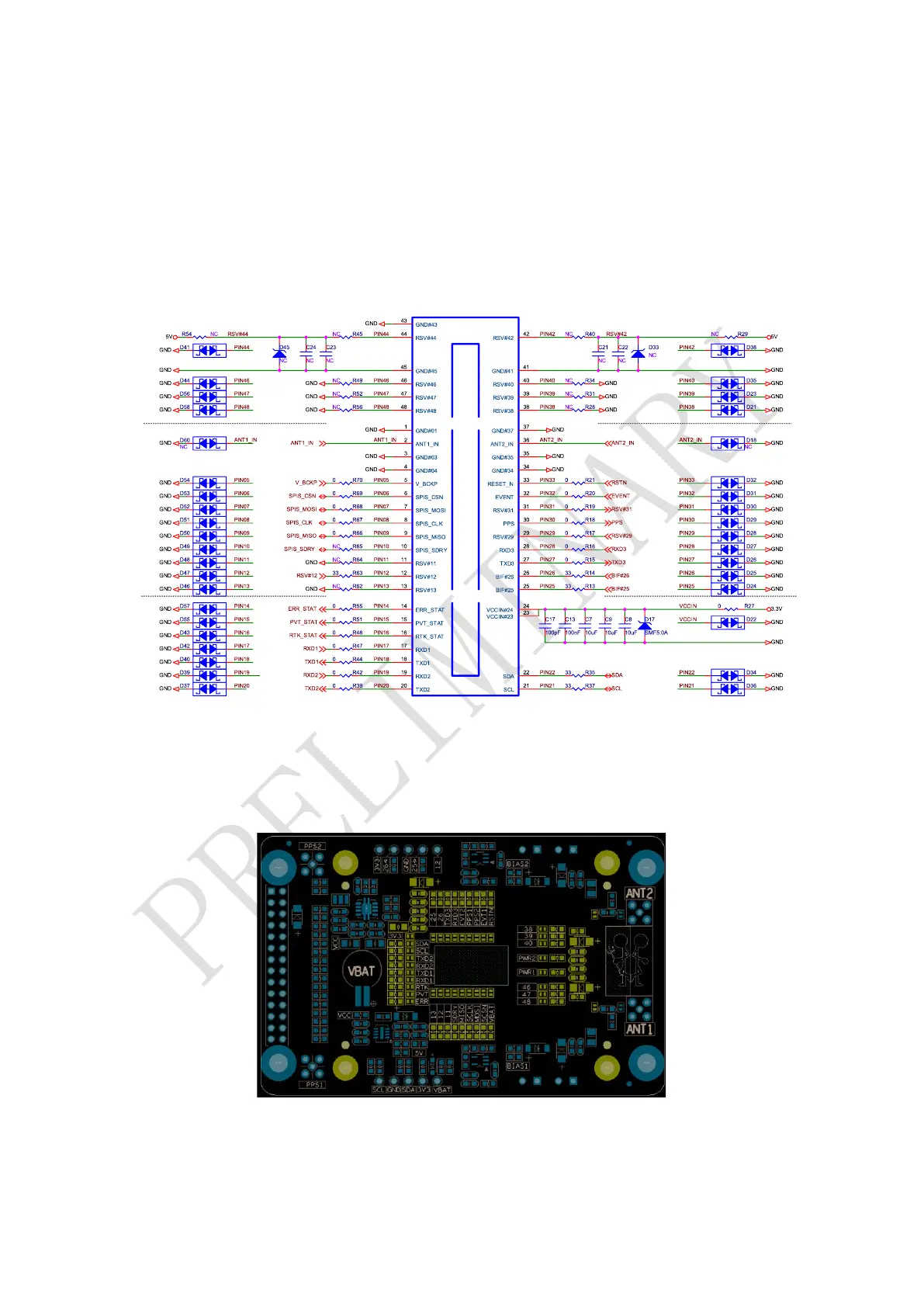
Figure 6-1 UM982 Peripheral Design
Silkscreen markings are printed around the UM982 module to identify the resistors, which
is convenient for measurement.
Figure 6-2 UM982 Peripheral Circuit
The GND pads at the bottom of the module should be grounded to ensure heat dissipation.