EasyManuals Logo

UNICORECOMM UM982-EB User Manual

Default Icon
26 pages
To Next Page IconTo Next Page
To Previous Page IconTo Previous Page
Page #9 background imageLoading...
Page #9 background image
UM982-EB User Manual
4 Interfaces UC-08-M31 EN P1.0.3
2 Interfaces
The dual-row 28 pins serve as the external interfaces of UM982-EB, and the pin pitch is
2 mm. The interfaces can be directly connected to the J18 on Unicore HPL EVK-V5.0
board.
J6
CH71283V100
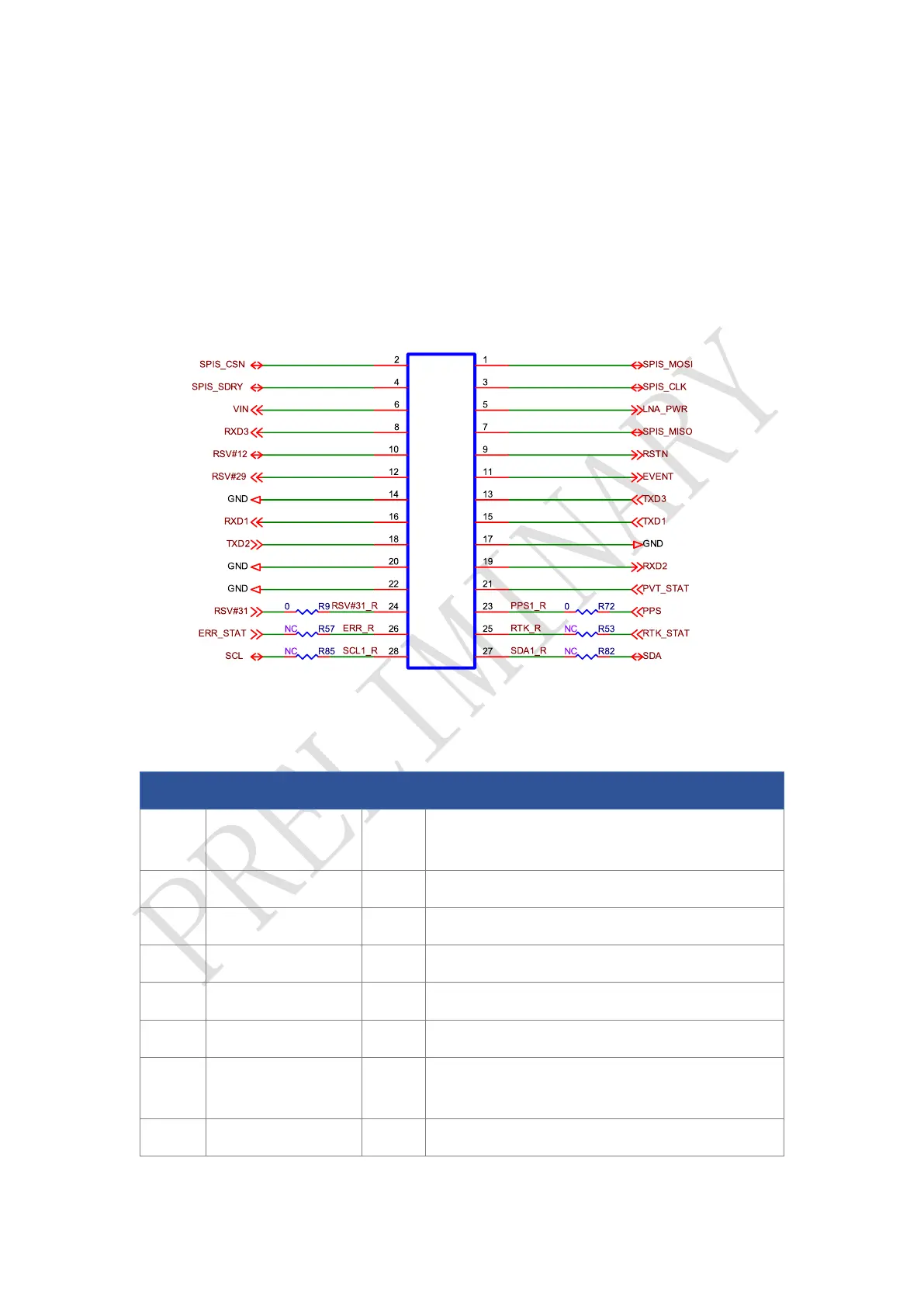
Figure 2-1 UM982-EB Interfaces
Table 2-1 UM982-EB Pin Description
No.
Pin Name
I/O
Description
1
SPIS_MOSI
I
Master Out / Slave In. This pin is used to receive
data in slave mode.
2
SPIS_CSN
I
Chip select pin for SPI slave
3
SPIS_CLK
I
Clock input pin for SPI slave
4
SPIS_SDRY
O
Interrupt output of SPI slave
5
LNA_PWR
I
Antenna feed voltage for LNA
6
VIN
I
Main power supply
7
SPIS_MISO
O
Master In / Slave Out. This pin is used to
transmit data in slave mode.
8
RXD3
I
COM3 input, can be used as CAN RXD, LVTTL

Questions and Answers:

Question and Answer IconNeed help?

Do you have a question about the UNICORECOMM UM982-EB and is the answer not in the manual?

UNICORECOMM UM982-EB Specifications

General IconGeneral
BrandUNICORECOMM
ModelUM982-EB
CategoryMotherboard
LanguageEnglish