Operation
WPP 15 E | Version 1.02 11
Step 1: position the support blocks on the press table.
Step 2: press the four pins in the support blocks down
on each side so they are fully inserted in the
press table.
This prevents the support blocks from slipping or tilting
during processing.
10.3 Adjusting the horizontal working position
Step 1: align the workpiece so that it is horizontal to the
hydraulic cylinder.
As a result, it cannot tilt during hydraulic cylinder pro-
cessing.
10.4 Aligning hydraulic cylinders
The hydraulic cylinder can be manually moved to the
desired position over the workpiece. For this purpose, it
can be moved towards the left or right.
10.5 Building up pump pressure
Step 1: move the switching valve to the right-hand posi-
tion to access the hydraulic cylinder for filling.
Step 2: move the pump lever and the pedal up and
down until the stamp comes into contact with the
workpiece. Fill the hydraulic cylinder with oil.
Step 3: continue to pump until the required pump pres-
sure has built up. For this purpose, monitor the
pressure gauge.
The pump pressure can also be built up using the pneumatic
foot-operated pump.
For this purpose, operate the pneumatic foot-operated
pump and proceed as described for the pump lever un-
til the required pressure has been built up.
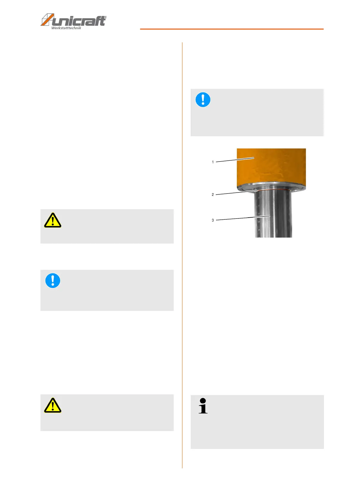
10.6 Marking the cylinder limit position
Fig. 9: Cylinder limit position mark on the piston rod
1 - Cylinder
2 - Limit position mark on the piston rod
3 - Piston rod
If the marking on the piston rod [2] becomes visible dur-
ing the pressing process, the pressing process must be
terminated to prevent potential damage to the cylinder.
In the event of non-observance and continued pumping
the cylinder will be damaged with the result that the cyl-
inder may no longer retract correctly.
Retract the cylinder if the pressing process was insuffi-
cient up to the mark (see section 10.7). In this case, ele-
vate the press table and repeat the pressing process
(from section 10.2).
10.7 Retracting hydraulic cylinders
IMPORTANT!
Make sure the workpiece has been centred under
the piston!
NOTE!
Monitor both the working area and the pressure
gauge during pressing to exclude potential damage
to the press or workpiece caused by overloads.
IMPORTANT!
- Do not exceed the press capacity!
- Do not use extensions for the pressure lever
NOTE!
Monitor both the work area and the piston rod during
the pressing process for the purpose of marking the
limit position to prevent potential damage to the cyl-
inders caused by overloads.
Tips and recommendations
The manufacturer has already configured the
retracting speed of the hydraulic cylinder. Modifica-
tions are required or permitted following mainte-
nance work or repairs only. For this reason, the
adjusting screw has been covered.