8 WPP 15 E | Version 1.02
Machine description
6 Machine description
Figures in these operating instructions may deviate from the
original.
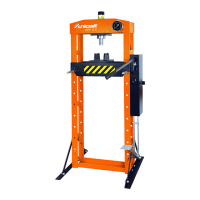
Fig. 4: WPP 15 E hydraulic workshop press
1 Hydraulic cylinder
2 Pressure gauge
3 Manual hydraulic pump
4 Pump lever for the manual hydraulic pump
5 Switching valve to move the hydraulic cylinder up/
down
6 Trigger valve
7 Pedal
8 Crossbeam feet
9 Frame
10 Press table support bolt
11 Press table
12 Support blocks
13 Stamp
6.1 Optional accessories
- Protective grille
- Pressure barb set
7Setup
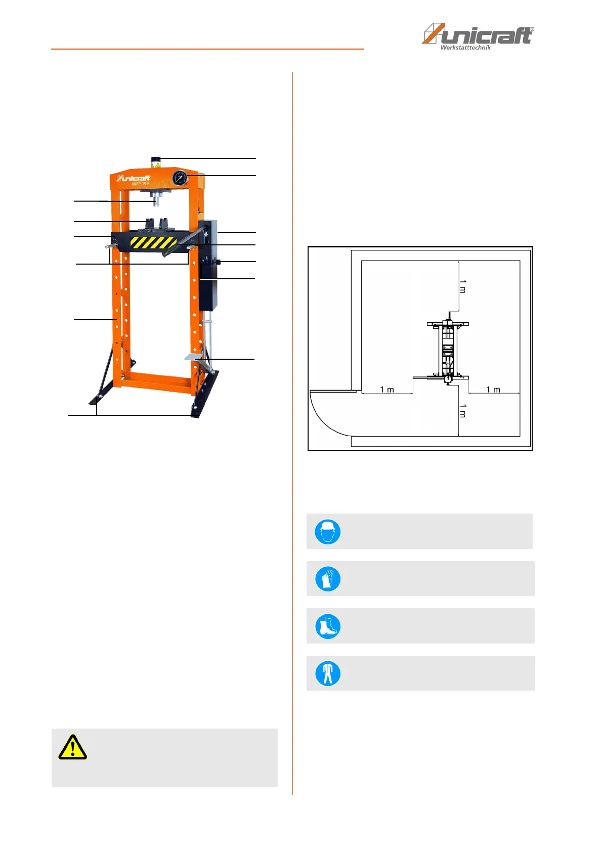
The hydraulic workshop press must be set up and oper-
ated in dry, well-ventilated indoor areas only.
It must be positioned securely and set up on an even,
stable surface that is free from vibrations and be se-
cured using suitable ground anchors.
Make sure there is a sufficient amount of clearance, ap-
proximately 1 m clearance on each side (see Fig. 6) and
the work area is adequately lit.
Fig. 5: Correctly set up the hydraulic workshop press
8Installation
IMPORTANT!
Do not exceed the maximum pressure of 15 tons
when using the pressure barb set.
Wear head protection!
Wear protective gloves!
Wear safety shoes!
Wear protective clothing!