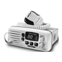
Indicators
9. 16 - Indicates that Channel 16 is selected.
10. INT - Indicates International Channel Mode.
11. LO - Indicates transmitted output is 1 Watt.
12. TX (Transmit) - Indicates PTT switch is pressed.
13. LED Numerical Channel Display - Indicates Channel Number in
use. Weather Channels are displayed as single digits (Example:
0, 1, 2, 3, etc.). Communication Channels are displayed as two
digits (Example: 01, 02, 03, etc.).
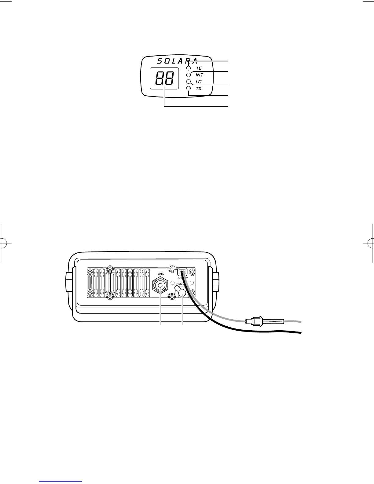
Rear Panel Connectors
14. ANT. (Antenna) Connector - Connect the antenna here using a
PL259 type connector.
15. REMOTE Speaker Connector - An external 4 ohm, 4 watt
speaker may be connected to this jack. The connecting wire must
use the included 3.5mm miniature plug.
16. DC Power Cord with In-line Fuse Holder - Connect red power
lead to positive power source.
17. DC Ground Cord - Connect black power lead to negative
power source.
 Loading...