Configuration Sageon Micro Power Module Manual
PM990-4207-00, Rev 6
2-5
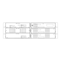
Figure 2.8 Connections on Controller backplane
Remote communications module connection (14-way ribbon)
Auxiliary peripheral module (relays, battery cell monitor, etc) connection (16-way ribbon)*
Battery (& load) distribution module connection** (34-way ribbon)
Ambient temperature sensor connection (sensor P/N 385-5941-03)
Battery temperature sensor connection (sensor P/N 385-5941-03)
Rectifier isolated communications connection (10-way ribbon)*
Standalone system voltage connection (Controller power and voltage sensing) – special use only
Load circuit breaker trip detection circuitry connection
Notes:
* Devices and cable connections are pre-wired as part of the supplied and tested Power shelf
** This connection can be left unused if the system has no requirement for control and maintenance of batteries (i.e.
standalone DC power supply)
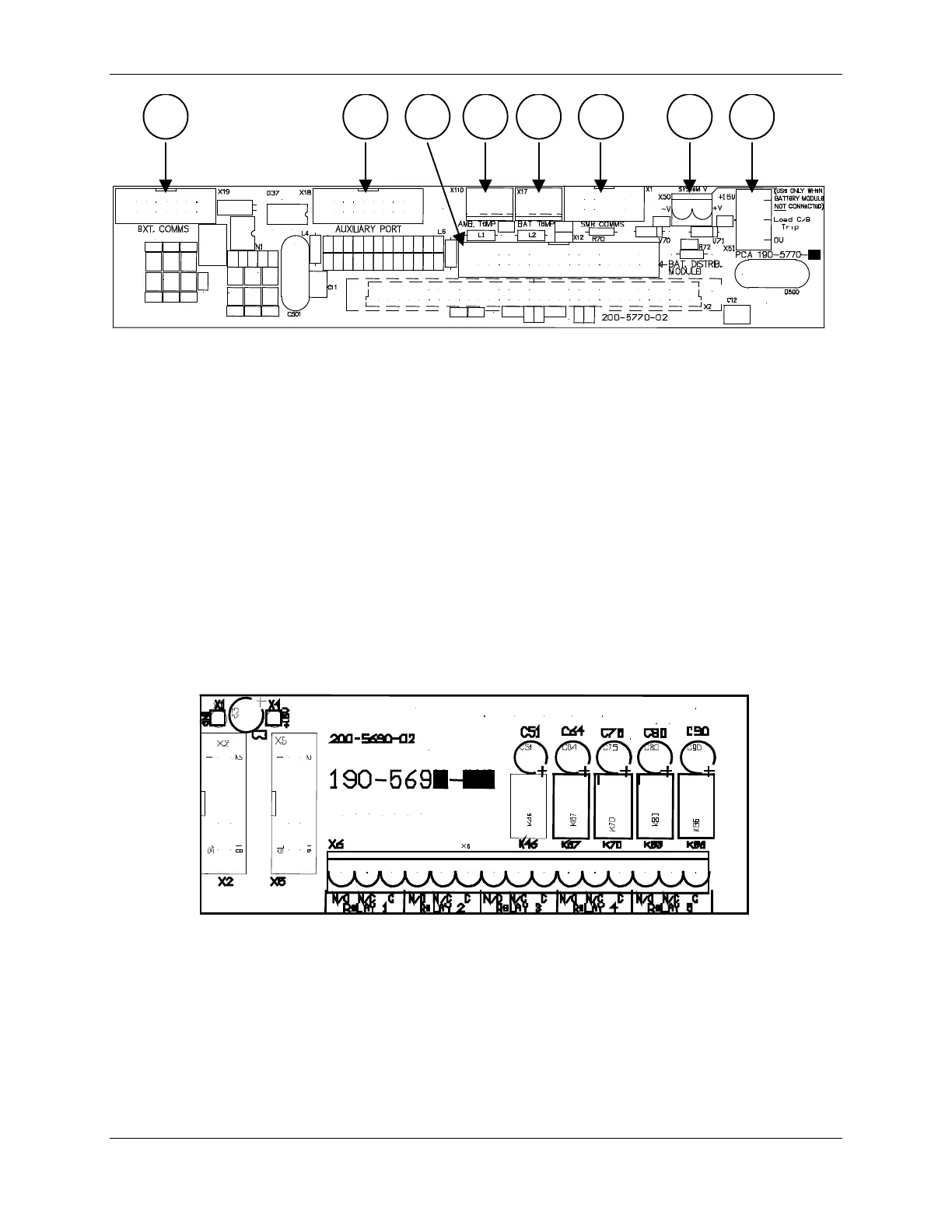
Figure 2.9 Alarm relay board connections
The alarm relay board is inverted when installed in the Power shelf lid such that Relay 5 is on the left when viewed
from the rear of the metalwork. The connections are labeled again on the rear cover. Each alarm is user
programmable through the Controller using the Sageview PC software.
 Loading...