Installation Sageon Micro Power Module Manual
PM990-4207-00, Rev 6
3-1
3. INSTALLATION
3.1 MOUNTING THE POWER SHELF
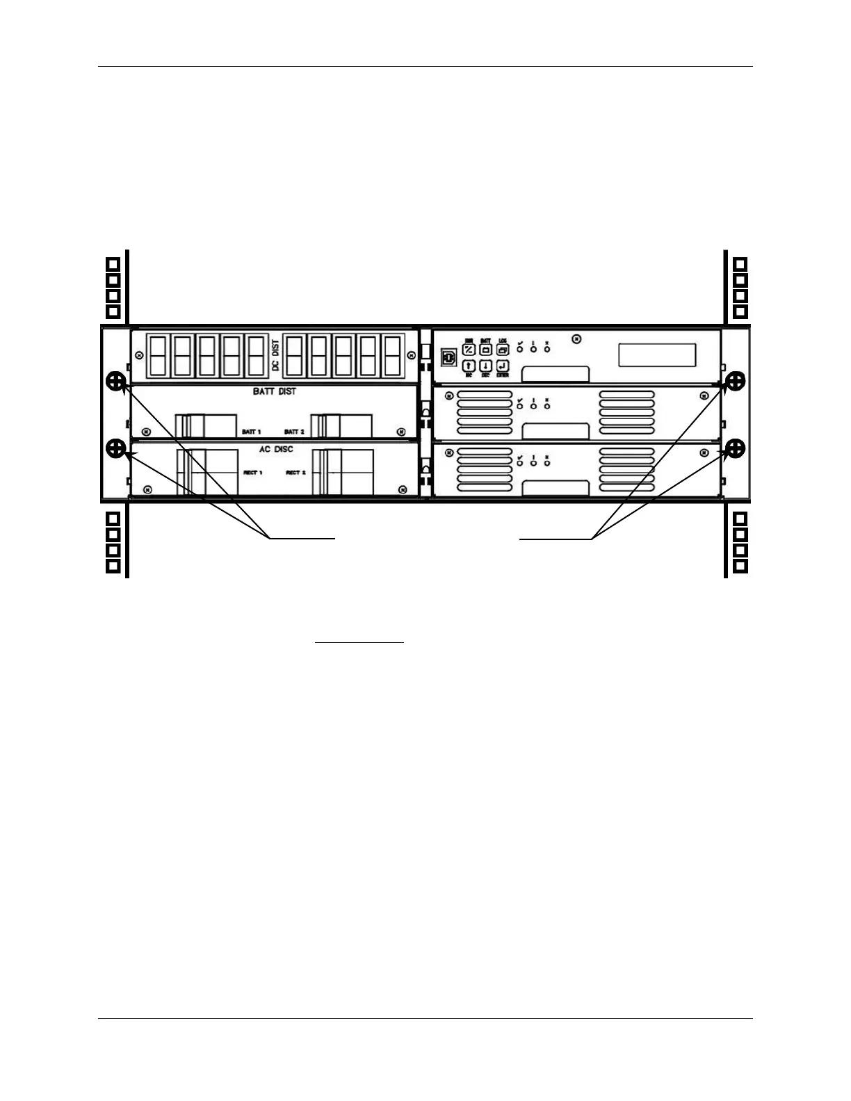
The Power shelf is mounted into a standard 19” rack using 12-24 screws. A minimum of 4 screws are required to
secure the Power shelf into the rack. It is recommended to initially install the Power shelf into the rack without
either the Controller or the RT9 rectifiers in place.
Figure 3.1 Mount points for securing Power shelf in a rack
Wiring for the standard power shelf is rear access only. For systems where rear access is not available, the Power
shelf can be pre-wired for load, battery, AC power and remote communications before mounting the magazine in the
rack. For maintenance and load expansion, the Power shelf is slid forward until the rear top cover is able to be
opened to access the wiring points with suitably tools.
3.1.1 Tools Required for Installation
• No. 2 screwdriver (for tightening rack bolts)
• No. 1 screwdriver
• 10mm open-ended spanner or socket (insulated for live DC work)
• 4mm Hex-bar driver allen wrench
• Small flat-blade screwdriver (for tightening DIN rail terminal screws)
3.1.2 Gaining Access to Rear Wiring
NOTE: Access to the rear wiring should be limited to qualified service personnel. It is recommended to remove the
AC power before gaining access to the rear wiring due to the safety hazard present inside the electrical enclosure.
 Loading...