32
Copyright 2011 Unitech Electronics Co., Ltd. All rights reserved. Unitech is a registered trademark of Unitech Electronics Co., Ltd.
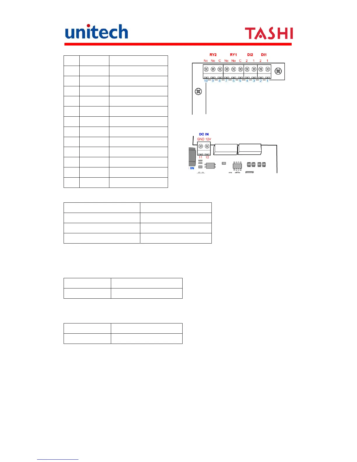
Terminal Block Pin Assignment
No. Name Description
1 DI1-1 Photo-In Cathode(+)
2 DI1-2 Photo-In Anode(-)
3 DI2-1 Photo-In Cathode(+)
4 DI2-2 Photo- In
5 RYI-C Common
6 RYI-No Normal Open
7 RYI-Nc Normal Close
8 RY2-C Common
9 RY2-No Normal Open
10 RY2-Nc Normal Close
11 GND GND
12 DC IN +12V, 2A
Relay
RL1 – CTRL High RY1(C & NC Linked)
RL1 – CTRL Low RY1(C & NO Linked)
RL2 – CTRL High RY2(C & NC Linked)
RL2 – CTRL Low RY2(C & NO Linked)
Digit Input
DI1-1 and DI1-2 are the positive and negative nodes of the external power
input.
DI1 = High Digit-Input1= High
DI1 = Low Digit-Input1= Low
DI2-1 and DI2-2 are the positive and negative nodes of the external power
input.
DI2 = High Digit-Input2= High
DI2 = Low Digit-Input2= Low