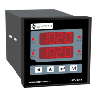
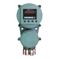
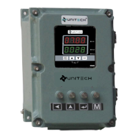
The UNITECH Model UT-102 is a Universal Process Indicator / Controller designed for various industrial applications. It is a panel-mounted device housed in a robust casing, with an optional flame-proof enclosure available for hazardous environments.
Function Description
The UT-102 serves as a versatile instrument for measuring, controlling, and displaying process parameters. It can accept a wide range of input signals from thermocouples (K, J, R, S, T, E), RTDs (Pt-100, Pt-1000, Cu-53 in 2 or 3-wire configurations), and analog signals (current: 4-20mA DC, 0-20mA DC, 0-5 Amp AC; voltage: 0.5-2.5VDC, 1-5VDC, 0-10VDC). Special on-demand linear inputs (0-75mV/0-200mVDC, 0-100/200/300VDC) are also supported.
The device features a double-row, 0.56" 4-digit, 7-segment red LED display for both Process Value (PV) and Set Value (SV). It provides alarm indication through front red LEDs for each relay and status LEDs for relay status and communication. The control mode is On/Off, with up to 4 relays available depending on the size. It also includes dead band controls for high and low set points, useful for level applications.
For output, the UT-102 offers NO-C-NC relay contacts (5A@240 VAC Resistive), SSR (Solid State Relay) voltage output (24VDC @ 20mA, 12VDC @ 20mA), and retransmission outputs (linear 0-20/4-20mA DC, 0-10 VDC). An isolated 24VDC@30mA transmitter power supply is also available.
Communication capabilities include Modbus RTU protocol via RS-485/RS-232, allowing connection of up to 128 units. Programmable parameters include setpoint, hysteresis, high/low scale, relay logic, and display resolution (-1999 to 9999).
Important Technical Specifications
Input:
- Type: T/C (K, J, R, S, T, E), RTD (Pt-100, Pt-1000, Cu-53 [2 or 3 wire]), Current (4-20mA DC, 0-20mA DC, 0-5 Amp AC), Voltage (0.5-2.5VDC, 1-5VDC, 0-10VDC), Special on-demand (0-75mV/0-200mVDC, 0-100/200/300VDC).
- Input Range:
- T/C: K (-50~1200°C), J (-50~750°C), R (0~1750°C), S (0~1750°C), T (0~400°C), E (-50~400°C).
- RTD: Pt-100 (-50~400°C).
- Current/Voltage/Special on-demand: -1999~9999 Display.
- Accuracy: T/C: ± 0.25% of Full Scale; RTD: Class A; Analog (V & I): ± 0.1% of Full Scale; Special on-demand: ± 0.1% of Full Scale.
- Cold Junction Compensation: Automatic software-based self-compensation.
- Sensor Break Info: "OPEn" or "OUEr" indication.
- Input Impedance: >330 K for Voltage, mV, T/C; 100 R for current.
Indication:
- Display: [PV]: 0.56" 4 Digit, [SV]: 0.56" 4 Digit, 7 Segment Red Display (Double row).
- Relay Status: Front Red LED for all Relay Alarm status.
- Status Indication: LEDs for Relay status & Communication.
- Alarm Modes: Low / High.
Control Mode:
- On Off control: Relay / SSR. Max.: 4 Nos.
- Dead Band controls: High and Low Set point for level application.
Output:
- Relay Output: NO-C-NC Contacts, 5A@240 VAC Resistive, up to 1 to 4 Relays.
- SSR [Volt] Output: 24VDC @ 20 mA, 12VDC @ 20 mA.
- Retransmission: Linear: 0-20/4-20mA DC, 0-10 VDC.
- Transmitter Power Supply: Isolated 24VDC@30mA, Max.
Communication:
- Protocols & method: Modbus RTU RS-485/RS-232.
- Prog. parameters: Baud rate, Parity, Node address, Stop bit.
- Max. Connections: Up to 128 Units.
General Specification:
- Power Supply: 110/240V AC, 50Hz, 12/24VDC (Optional on demand).
- Power Consumption: 4 Watts Maximum.
- Operating Ambient: Temp.: 0~50°C, Humidity: Below 90% Non condensing.
- Enclosure [If Reqd.]: FC-1 [1-Compartment] OR FC-2 [2-Comp.] : IIA, IIB Exter. keys & Cable Entries (Flame Proof).
Dimensions:
- Model UT-102: A=96, B=96, C=10, D=100, E=90, a=90±0.5, b=90±0.5, c=120, d=120 (all dimensions in mm).
Usage Features
The UT-102 offers a user-friendly operation interface with dedicated keys for "PASS," "UP," "MODE," and "ENTER." It supports multiple operational modes:
- Configuration Mode: Allows setting input type, alarm relay activation, decimal point, node address, baud rate, parity, cycle type for linear input, offset, and gain for input. Password protected.
- Setup Mode: Configures setup mode password, zero/low display value, span/high display value, alarm set points (SP1, SP2, SP3, SP4), hysteresis for alarms, offset to process value, and output low/high for analog output. Password protected.
- Calibration Mode: Used for calibration of zero/low input, span/high input, low retransmission output, high retransmission output, and ambient temperature compensation for thermocouples. Password protected.
- Change Password Mode: Allows users to change the password for accessing different modes.
The device features automatic software-based cold junction compensation for thermocouples and displays "OPEn" or "OUEr" for sensor break information. The display resolution is fully configurable from -1999 to 9999 for linear inputs.
Maintenance Features
The UT-102 is designed for reliable operation with minimal maintenance.
- Self-compensation: Automatic software-based cold junction compensation reduces the need for manual adjustments.
- Error Messages: The device provides clear error messages on the display (e.g., "OPEn" for open input connection, "OUEr" for excess PV over span, "undr" for shortage of PV over low value, or all LEDs and display not light for power/controller failure) to assist in troubleshooting.
- Modular Design: The panel-mounted design allows for relatively easy installation and replacement.
- Password Protection: Critical configuration and calibration parameters are password-protected to prevent unauthorized changes and ensure system integrity.
- Technical Support: In case of persistent issues, users are advised to refer to the error message table or contact technical support.
Safety Precautions:
- Installation should be performed by qualified personnel in accordance with local regulations and the provided wiring diagram.
- The controller is designed for "Rack and panel mounted equipment" per EN 61010-1.
- Applying 240V AC to a controller rated for 12-24VDC will severely damage the controller and is a fire and smoke hazard.
- Shielded twisted pair cable is required for all analog input & output, process variables, RTD, thermocouple, DC volts-mV, low level signal, mA, alarm outputs, and computer communication interface circuits.
- A switch, fuse (1/2A, 250V) or a circuit breaker (1A, 125A) is required for the power supply.
- Configuration should only be performed by technically competent personnel. Failure to comply with instructions could result in death or serious injury.