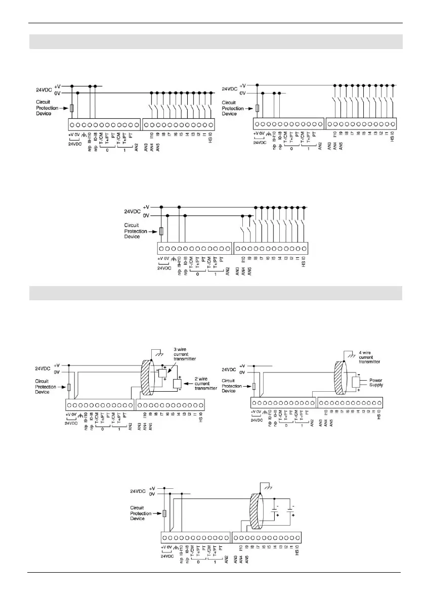
Digital Inputs, Controller’s Power Supply
Note: The inputs are arranged in two groups. You can wire one group as npn and the other as pnp,
or wire both groups as npn, or as pnp. In either case, the npn/pnp pins must be connected.
Input wiring, pnp (source)
Input wiring (I0-I8), pnp (source), (I9-I10), npn (sink)
Note: Shields should be connected at the signal source.
Analog Input wiring, current, 2 or 3 wire, AN2
and AN3
Analog Input wiring, current, 4 wire, AN2 and
AN3
Analog Input wiring, voltage, AN4 and AN5
Note: If either I9 or I10 is wired as an npn digital input, the remaining input may not be wired as an
analog input.
 Loading...