Vision™ OPLC™ Installation Guide
8 Unitronics
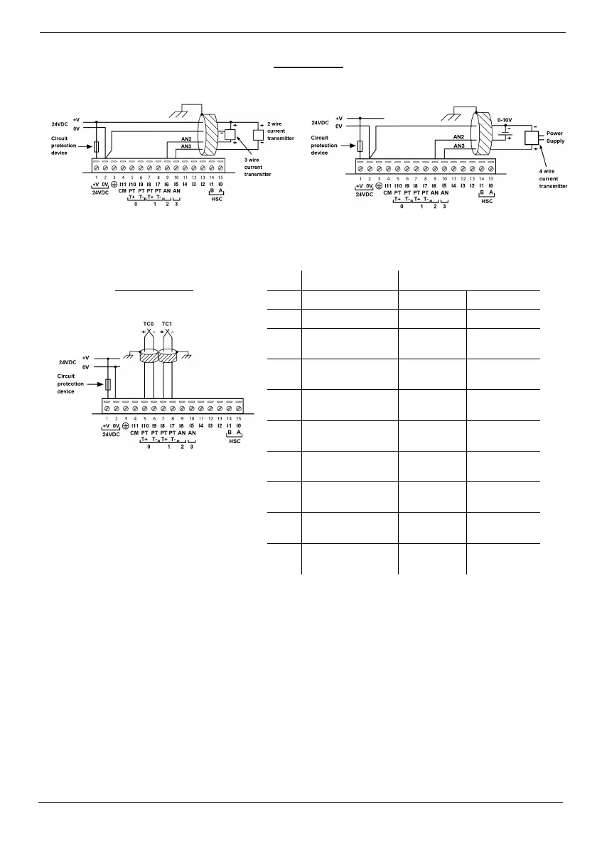
Analog Input
Analog input wiring, current (2/3 wire) Analog input wiring, current (4-wire), and voltage
Shields should be connected at the signal’s source.
The 0V signal of the analog input must be connected to the controller’s 0V.
Thermocouple
Type
Temp. Range Wire Color
ANSI (USA)
BS1843 (UK)
mV -5 to 56mV
B
200 to 1820˚C
(300 to 3276˚F)
+Grey
-Red
+None
-Blue
E
-200 to 750˚C
(-328 to 1382˚F)
+Violet
-Red
+Brown
-Blue
J
-200 to 760˚C
(-328 to 1400˚F)
+White
-Red
+Yellow
-Blue
K
-200 to 1250˚C
(-328 to 2282˚F)
+Yellow
-Red
+Brown
-Blue
N
-200 to 1300˚C
(-328 to 2372˚F)
+Orange
-Red
+Orange
-Blue
R
0 to 1768˚C
(32 to 3214˚F)
+Black
-Red
+White
-Blue
S
0 to 1768˚C
(32 to 3214˚F)
+Black
-Red
+White
-Blue
T
-200 to 400˚C
(-328 to 752˚F)
+Blue
-Red
+White
-Blue
Thermocouple 0: use Input 9 as
negative input and 10 as positive.
Thermocouple 1: use Input 7 as
negative input and 8 as positive.