EasyManuals Logo

Unitronics Vision OPLC V1040-T20B User Manual

Unitronics Vision OPLC V1040-T20B
13 pages
To Next Page IconTo Next Page
To Previous Page IconTo Previous Page
Page #10 background imageLoading...
Page #10 background image
Vision™ OPLC™ V1040-T20B
Installation Guide
10
Unitronics
CANbus
+
-
-V
L
PE
H
+V
Circuit
protection
device
-V
L
PE
H
+V
-V
L
PE
H
+V
121
terminating
resistor
121
terminating
resistor
Power Supply
These controllers comprise a CANbus port. Use
this to create a decentralized control network using
one of the following CAN protocols:
CANopen: 127 controllers or external
devices
CANLayer 2, J1939
Unitronics’ proprietary UniCAN: 60
controllers, (512 data bytes per scan)
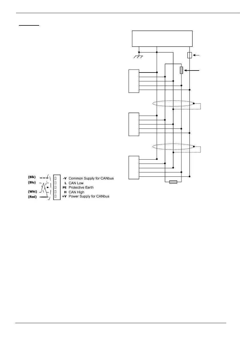
The CANbus port is galvanically isolated.
CANbus Wiring
Use twisted-pair cable. DeviceNet® thick shielded
twisted pair cable is recommended.
Network terminators: These are supplied with the
controller. Place terminators at each end of the
CANbus network.
Resistance must be set to 1%, 121Ω, 1/4W.
Connect ground signal to the earth at only one
point, near the power supply.
The network power supply need not be at the end
of the network
CANbus Connector

Other manuals for Unitronics Vision OPLC V1040-T20B

Questions and Answers:

Question and Answer IconNeed help?

Do you have a question about the Unitronics Vision OPLC V1040-T20B and is the answer not in the manual?

Unitronics Vision OPLC V1040-T20B Specifications

General IconGeneral
BrandUnitronics
ModelVision OPLC V1040-T20B
CategoryController
LanguageEnglish

Related product manuals