**Causes the unit to function as an end unit in an RS485 network
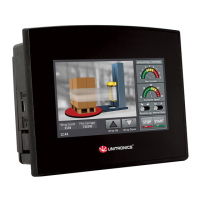
Installing a Snap-in I/O Module
▪ Before installing a Snap-In Module, ensure that the Communication Module Cover is
closed.
1. Remove the I/O connector cap shown on Page 6.
2. Line the circular guidelines on the Snap-in I/O Module with the slots on the controller as shown
below.
3 Apply even pressure on all 4 corners until you hear a distinct ‘click’. The module is now installed.
Check that all sides and corners are correctly aligned.
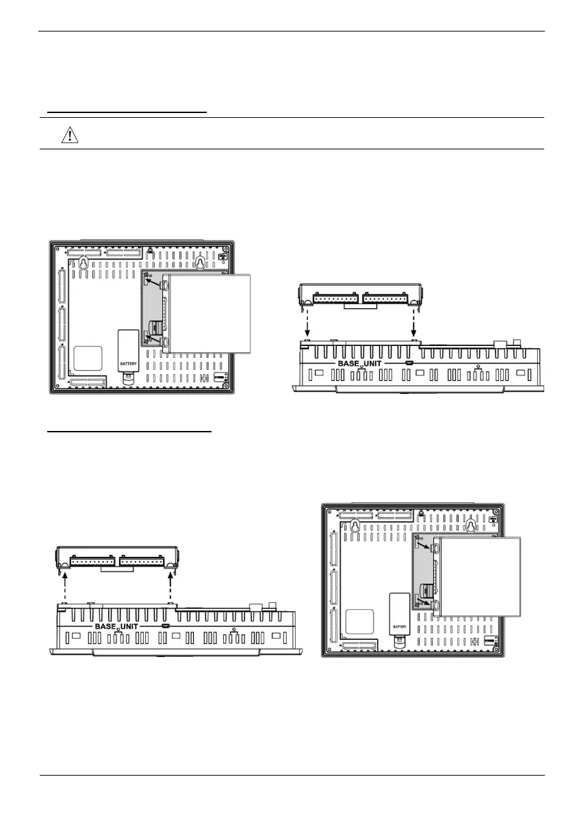
Removing a Snap-in I/O Module
1. Locate the four buttons on the sides of the controller, two on either side.
2. Press the buttons and hold them down to open the locking mechanism.
3. Gently rock the module from side to side, easing the module from the controller.