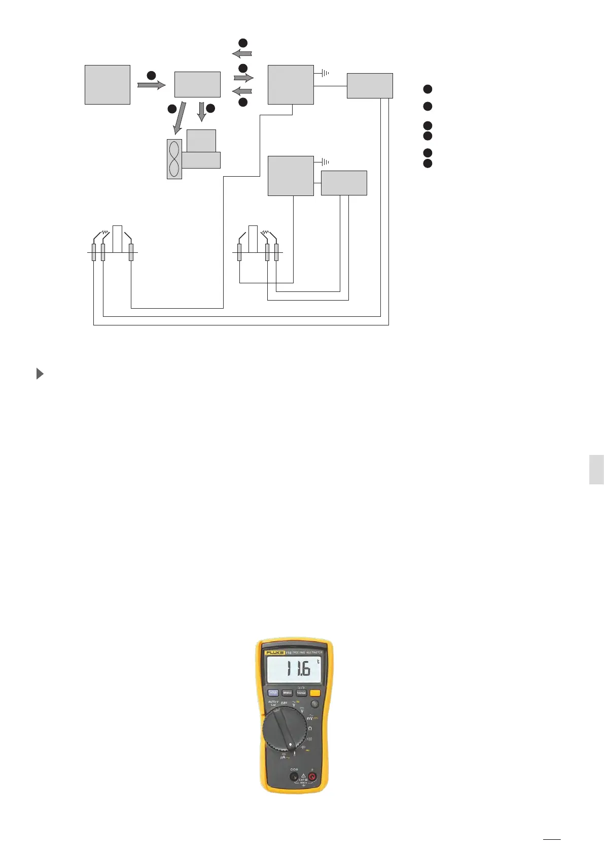
FLAME
CONTROL
BOARD 1
IGNITER
1
IGNITER
2
FLAME
CONTROL
BOARD 2
CONTROL
BOARD
HEAT DEMAND
GAS
VALVE
1
1
START IGNITION CYCLE
+ SPARK IGNITION
2
BLOWER POWER
CONTROL SPARK
3
4
GAS VALVE OPENING
5
6
2
3
5
6
4
POWER
BOARD
AC-DC
120V AC
Ignition sequence for US system
Maintenance of the electric part of the gas system
The US flame control board has an automatic diagnostic system. During different working conditions
the flame control board shows multiple working status by means of multi-color LEDs:
■ Steady green light, good status/flame sensed;
■ Steady o
r
an
g
e
light, start up status;
■
Steady
red
light, stop/gas block status;
■ Flashing
green
light, working status with weak ionizing signal;
■ Flashing
orange
light, start up status with good ionizing signal;
■ Flashing
red
light, diagnostic stop status or parasitic flame current;
■ Green and orange alternating light, start up status with weak ionizing signal;
■ Red and orange alternating light, low/high voltage signal.
During the start up the system normally shows steady orange – flashing orange – steady green light.
The system attemps three startup cycles every 5 seconds. The US gas oven has 2 flame control boards that
work synchronized. The European flame control board does not use a diagnostic system.
■ Ionization current;
■ Blower speed;
■ Visual check of the harnesses of the ignition and flame detection cables and electrodes.
The suggested instrument to perform these measurements is the Multimeter model: Fluke 116, see .
Multimeter TRUE RMS FLUKE 116 with Microamps
 Loading...