4G PRIMARY
ALARM COMMUNICATOR
14
INSTALLATION (cont.)
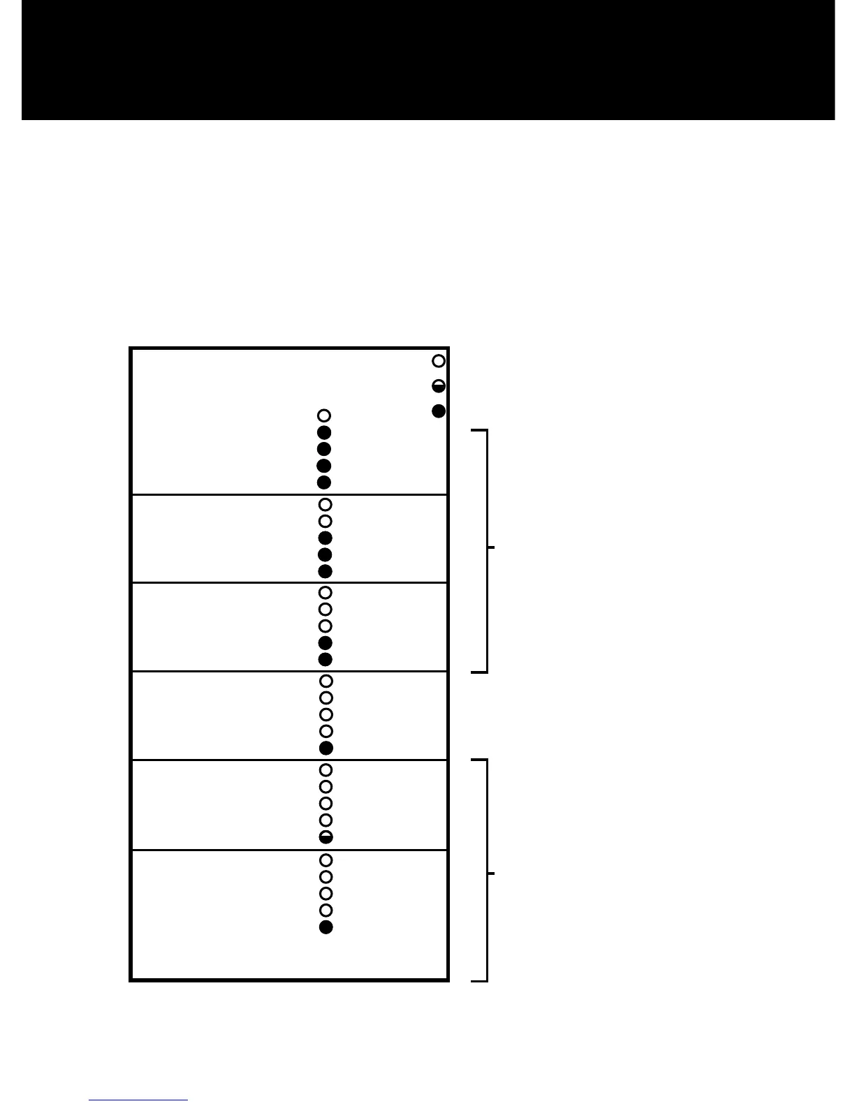
RSSI Mode: When the 4530 is placed in Received Signal Strength Indicator (RSSI)
ModebyturningDipswitchS4toON,theveLEDsindicatethefollowsignal
strength information:
GOOD
UNACCEPTABLE
MINIMUM
ACCEPTABLE
00-25593-006
D
Rev
A
Uplink 25x0
September 22, 2008 Sheet 1 of 1
Size
Label, RSSI Legend
BA CDE
1
2
3
4
1
2
3
4
B
A CDE
General Notes
1 - All measurements are +/- 0.010 inches.
2 - Must comply with UL 969 for marking and labeling systems.
3 - Color: black on white background.
4 - Unless specified, Font: Arial. Font Size: 6pt.
5 - Border line for reference only. Do not print
Rev
A
Date
9/22/08
ECO Reason
Initial Manufacturing Release
Eng
NP
Revision History
B
10/15/08
Correct Misspell
NP
Scale: 1:1
1.5
3
Font Size: 8pt.