5. Position the bottom of the 4530 enclosur
e where it will be installed. Use
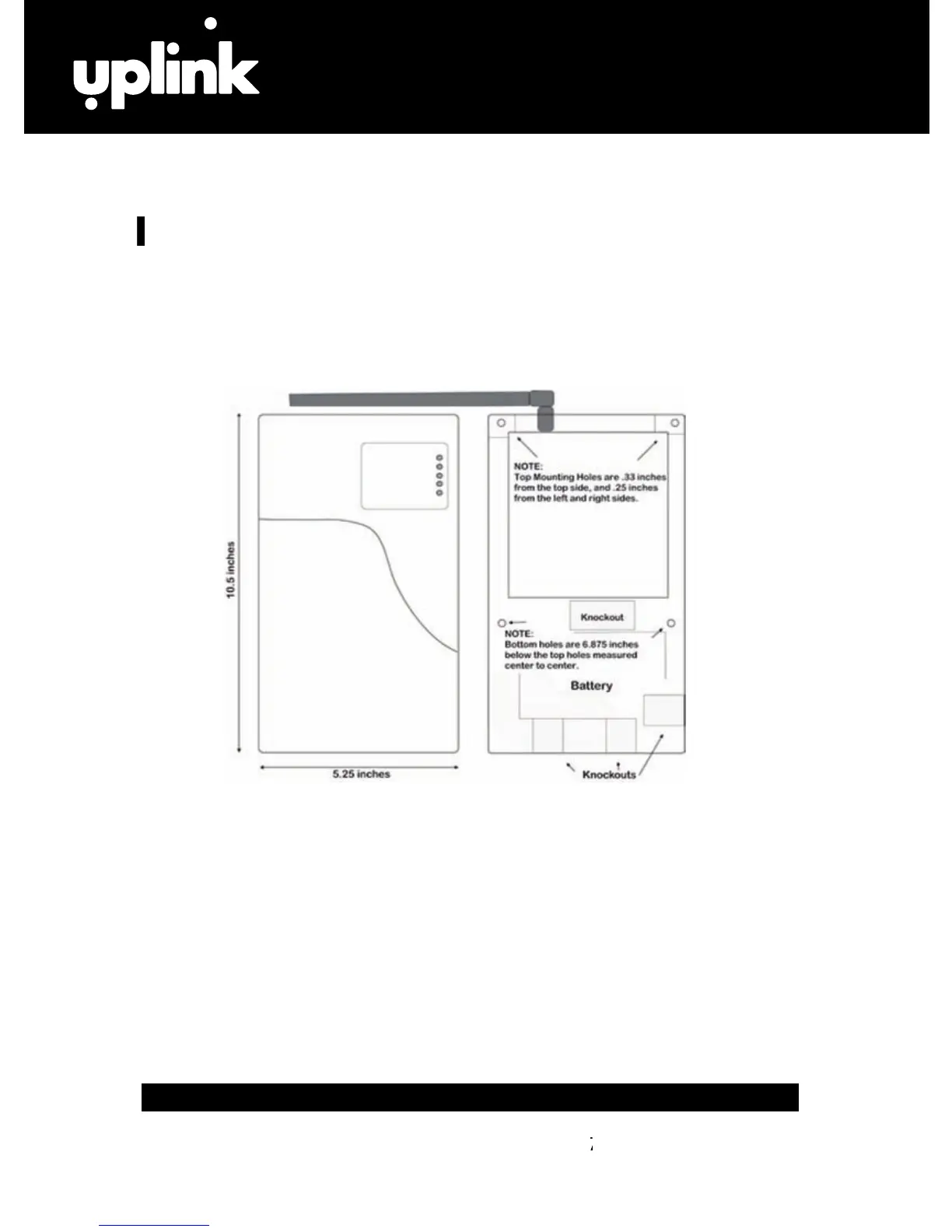
ews and mount the unit using the four holes in the enclosure’s
plastic bottom. The 4530’
s dimensions are shown in Figure 2.
e that the unit’s antenna is connected.
Connect the positive (+) and negative (-) terminals of the 12V DC power supply
to terminals DC+ and DC - r
8. Double check to make sur
e that the RSSI is still showing a good signal
n Dipswitch #4 (S4) to the OFF position.
b. Disconnect the Positive and Negative connections to the DC power sour
FIGURE 2: Inside & Outside Mounting Dimensions for the 4530
CAUTION: Incorrect Connections May result in Damage to the Unit
ALLATION continued next page)
(INSTALLATION continued next page)(INST