Section
3-21SB60 Work Platform
Maintenance
3.14
3.14 Axle Lock Cylinder
Removal
Note: Boom should be in fully lowered position
before performing this operation.
1. Mark and disconnect hoses and immediately cap
the openings to prevent contamination.
2. Remove hardware which secures axle lock cylinder.
Remove cylinder.
DISASSEMBLY
Note: Provide a clean work area for this operation,
and observe clean assembly practices. Seals and
hydraulic cylinder components are highly sensitive to
contamination that may not be visible to the naked
eye.
1. Unscrew head from cylinder
2. Carefully pull shaft assembly from cylinder.
3. Secure rod end and turn locknut off of rod.
4. Remove piston and slide the head off of the rod.
5. Remove seal kit components (wipers, rod seals, o-
rings and backup rings) from head and piston.
6. Thoroughly clean all parts with solvent. Rinse the
inside of the tube and allow to drain. A high pres-
sure rinse and wipe with a lint free rag is preferable.
7. Inspect cylinder parts for scratches, pits, or polish-
ing. Check seal groves and sealing surfaces.
Scratches or pits deep enough to catch the fingernail
are unacceptable, replace the cylinder. Polishing is
a sign of uneven loading. When this occurs, the
surface should be checked for roundness. Cylinders
not round within .007" should be replaced.
ASSEMBLY
NOTE: Torque all hardware to torques listed on page
3-29 unless otherwise specified.
1. Lubricate all components and seals with clean
hydraulic oil prior to assembly.
Note: To avoid cutting the seals, do not use sharp
edged tools during seal replacement. After installing
seals allow at least one hour for the seals to elasti-
cally restore to their original shape before assembling
cylinder.
2. Install new seal kit items to piston and head.
3. Lubricate rod wiper and seal with hydraulic oil and
slide head onto rod.
4. Install piston and locknut (torque locknut to 175-200
ft/lbs) onto rod.
5. Lubricate seals on piston and head with hydraulic
oil.
6. Carefully slide rod assembly into cylinder.
7. Thread head into cylinder.
INSTALLATION
1. Follow steps from "REMOVAL" section in reverse
order to install cylinder.
2. Slowly cycle cage rotate cylinder several times.
Check hydraulic connections for leaks. Check for
proper cylinder operation.
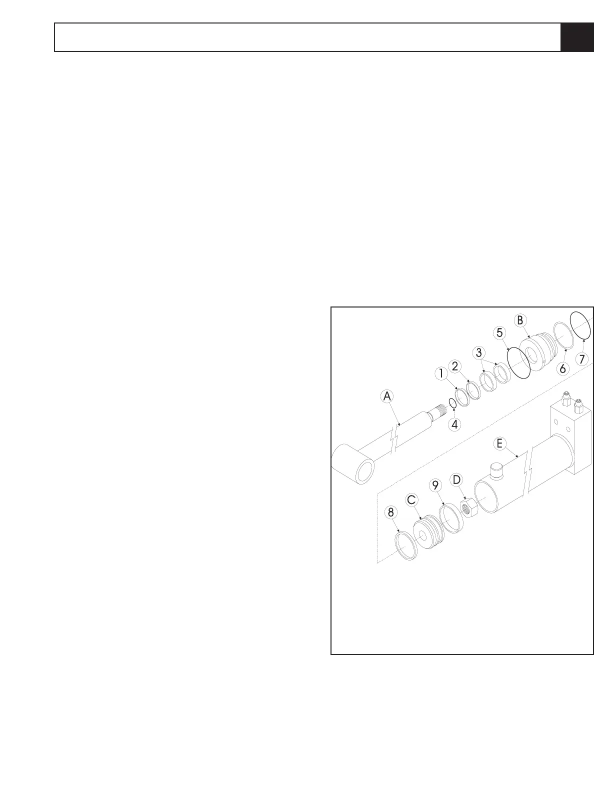
Figure 3-20: Axle Lock Cylinder
1. O-Ring
2. Wiper
3. Seal
4. Wear Ring
5. O-Ring
6. Back-up
7. O-Ring
8. Seal
9. Wear Ring
A. Rod
B. Head
C. Piston
D. Locknut
E. Cylinder
F. Washer Seal
G. Bleeder Plug
Seal kit (100556-010) includes:
3.14
 Loading...


