Do you have a question about the Upright MX19 and is the answer not in the manual?
Defines hazard symbols (Danger, Warning, Caution) and their meanings.
Outlines standard procedures, safety principles, and service operations for UpRight Inc.
Provides torque values for hydraulic components, SAE, and Metric fasteners.
Explains how to identify manufacturing dates on Gates, Parker, and Dayco hoses.
Lists specialized tools required for maintenance procedures on the machine.
Instructions for replacing UpRight connector parts without replacing the entire connector.
Procedure for removing, disassembling, cleaning, and assembling hydraulic manifolds.
Detailed steps for removing, disassembling, inspecting, and assembling cylinders.
Troubleshooting, disassembly, inspection, and reassembly of electric motors.
Guidance on checking electrolyte levels, cleaning terminals, and general battery care.
Information on checking fluid level and recommended hydraulic fluids for UpRight machines.
Defines floor loading and provides formulas for calculating localized and occupied pressure.
Procedures for preserving the machine during long-term storage, including cleaning and battery care.
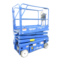
Overview of the MX15 and MX19 aerial work platforms, their function, and operation.
Procedures for periodic visual and operational checks to ensure proper machine performance.
Instructions for installing and storing the elevating assembly brace for safe maintenance.
Details on battery maintenance, checking electrolyte, replacement, and wiring.
Procedures for adjusting and testing Level Sensor and Proximity Switch for proper operation.
Guidance on checking fluid level and replacing the hydraulic fluid and filter.
Procedures for setting main relief, lift relief, and steering relief valves.
Instructions for removal, repair, and installation of the hydraulic manifold components.
Procedures for removing and installing the hydraulic pump assembly.
Steps for removing, installing, and servicing hydraulic drive motors.
Detailed instructions for removing, repairing, and installing the steering cylinder.
Procedures for removing, repairing, and installing the depression mechanism cylinder.
Instructions for removing, installing, and repairing the lift cylinder assembly.
Contact information for UpRight technical support via phone or FAX.
General steps for diagnosing and troubleshooting machine faults using schematics and tables.
Step-by-step guide to verify, narrow down, and resolve malfunctions.
Default and adjusted dip switch settings for the motor controller for creep speed and deceleration.
Default and optional dip switch settings for the I/O board, controlling alarm functions.
Interpreting LED fault codes on the motor controller for diagnostics.
Explanation of Green and Red LED indicators on the I/O board for power and shorts.
Voltage readings and conditions for I/O board connectors J1-J5.
Electrical troubleshooting table correlating components to functions and potential issues.
Hydraulic troubleshooting table correlating components to functions and potential issues.
Diagrams and legend for electric components and schematics.
Diagrams and legend for hydraulic components and schematics.
| Brand | Upright |
|---|---|
| Model | MX19 |
| Category | Lifting Systems |
| Language | English |