Hydraulic Manifold Section 2 - Service and Repair
Page 2-18 113101-000 MX15 / MX19 | Service Manual
2-8 H
YDRAULIC
M
ANIFOLD
It is not necessary to remove the manifold to perform all maintenance procedures. Decide beforehand as
to whether or not the manifold should be removed before maintenance procedures begin.
R
EMOVAL
, R
EPAIR
AND
I
NSTALLATION
Refer to
Section 1 - General Information
for removal, repair and installation instructions.
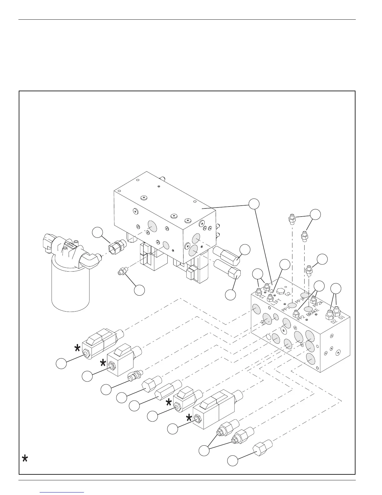
Figure 2-12:
Hydraulic Manifold
Front
Bottom
Right
5
7
4
3
1
2
9
6
8
10
11
12
13
14
15
16
17
18
19
20
Coils oriented with spades away from work ports
To p
(Mounting Surface)
Left
Rear
1.
Hydraulic Manifold
2.
Fitting, Straight 6MB - 6MJ
Lift Cylinder Port
3.
Fitting, Straight 4MBH - 4MJ
Steering Cylinder Ports
4.
Fitting, Straight 4MB - 4MJ
Depression Cylinder Ports
5.
Fitting, Straight 4MB - 4MJ W/ .031 Orifice
Depression Cylinder Ports
6.
Fitting, Straight 4MB - 4MJ W/ .031 Orifice
Brake Port
7.
Fitting, Straight 6MB - 6MJ
Drive Motor Port
8.
Fitting, Straight 6MB - 6MJ
Pressure Port (from hydraulic pump)
9.
Fitting, 8MB-8FJX
Return Port (to reservoir)
10.
Steering Relief Valve
11.
Flow Divider Valve
12.
Steering Solenoid
3 Position - 4 Way Solenoid W/ Coils
13.
Lift Solenoid
2 Position - 4 Way Solenoid W/ Coil
14.
Gauge Fitting
Te s t Po r t
15.
Check Valve
16.
Main
Relief Valve
17.
Depression Mechanism Valve
2 Position Poppet Valve W/ Coil
18.
Drive Solenoid
3 Position - 4 Way Solenoid W/ Coils
19.
Counterbalance Valve
20.
Lift Relief Valve