Section 2 - Service and Repair Steering Cylinder
113101-000 MX15 / MX19 | Service Manual Page 2-23
2-11 S
TEERING
C
YLINDER
R
EMOVAL
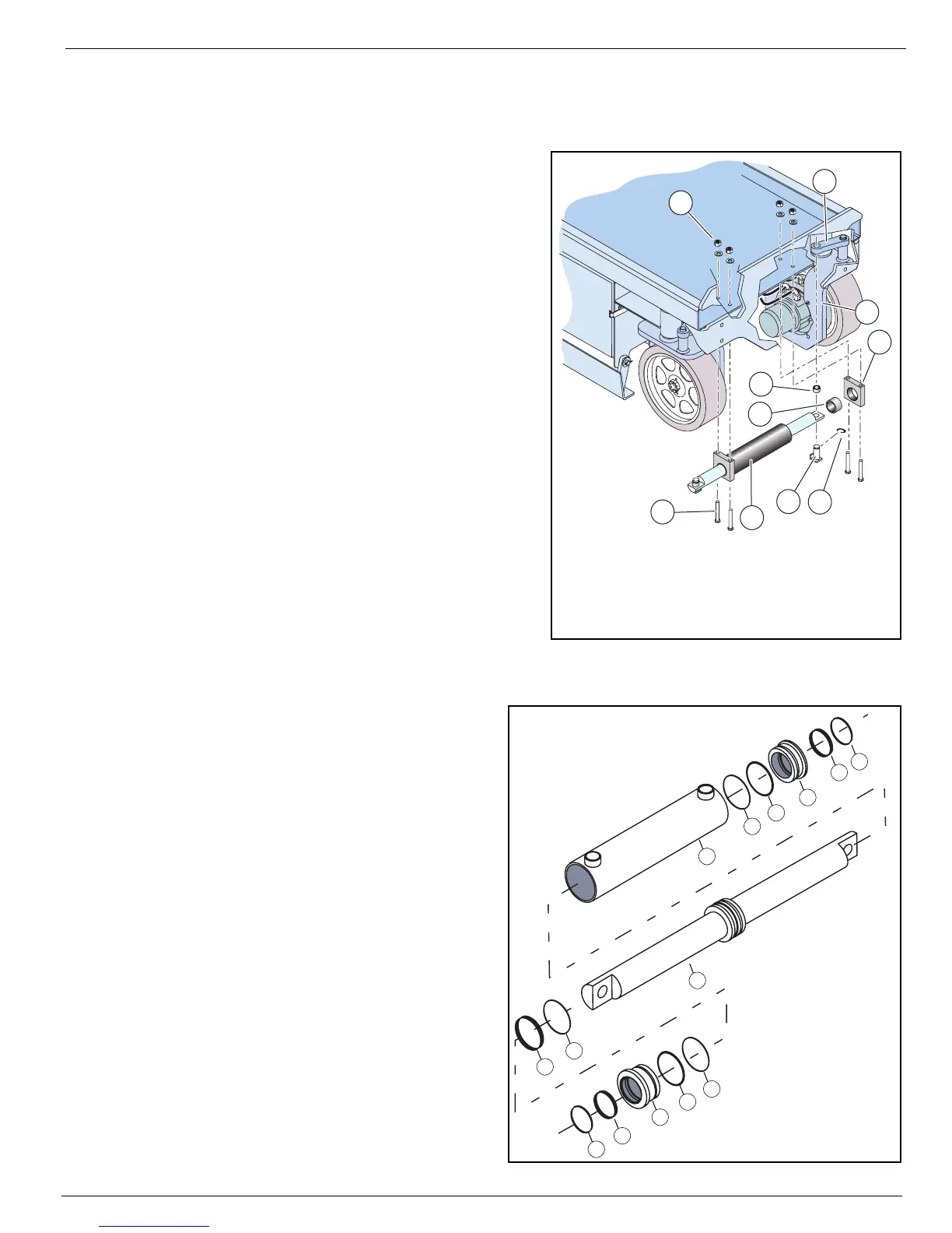
Figure 2-17:
Steering Cylinder Installation
1. Turn the wheels to the straight position.
IMPORTANT: Before disconnecting any hoses, thoroughly
clean off all the outside dirt around the fittings.
IMMEDIATELY plug the holes after disconnecting the
hoses and before removing the cylinder from the
machine.
2. Elevate the platform and block the elevating
assembly with the brace (see “Blocking the Elevat-
ing Assembly” on page 2-6).
3. Tag and disconnect the hose assemblies from the
cylinder fittings and immediately cap the openings
to prevent foreign material from entering.
4. Remove the retaining rings from the pivot pins.
5. While supporting the cylinder, remove the lock-
nuts, washers, and capscrews.
6. Remove the cylinder.
R
EPAIR
Refer to
Section 1 - General Information
for disas-
sembly, cleaning and inspection, and assembly
instructions.
I
NSTALLATION
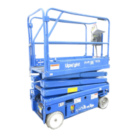
Figure 2-18:
Steering Cylinder Assembly
1. Position the cylinder assembly in the chas-
sis.
2. Insert the capscrews into the steer guide/
cylinder mounts, up through the chassis,
and secure with washers and locknuts.
IMPORTANT: If capscrews are inserted down through
the chassis the ends of the capscrews will
protrude through the bottom of the steer guide/
cylinder mount and may rub and cut the hydraulic
hoses.
3. Insert pivot pins and secure with retaining
rings.
4. Connect the hose assemblies to the fittings.
5. Operate the steering circuit several times
throughout its entire range of travel to expel
trapped air, then check for leaks.
9
4
5
7
1
10
6
8
3
2
1. Steering Cylinder
2. Steering Link
3. Pivot Pin
4. Retaining Ring
5. Bearing
6. Steer Guide/Cylinder
Mount
7. Bearing
8. Capscrew
9. Locknut and Washer
10. Wheel Yolk
A
B
B
C
1
1
2
2
3
3
4
4
5
6
A. Tube Assembly
B. Head
C. Rod and Piston
Seal Kit Includes:
Description Qty
1. Back-up 2
2. O-Ring 2
3. Seal 2
4. Wiper 2
5. Wear Ring 1
6. Seal 1