BASIC SYSTEM DIAGRAMS
INSTRUCTIONS FOR URMET DOMUS DEVICE INTERCHANGEABILITY
16
−−−−
sec.1f
DOOR PHONE - VIDEO DOOR PHONE SYSTEMS: Installation Diagrams
REPLACING RELAY BOXES Ref. 9332/1, Ref. 4330/31 and Ref. 788/1 WITH Ref. 788/1
REPLACING SUPPLEMENTARY VIDEO DOOR PHONE POWER UNIT Ref. 7073/5A
WITH Ref. 789/2
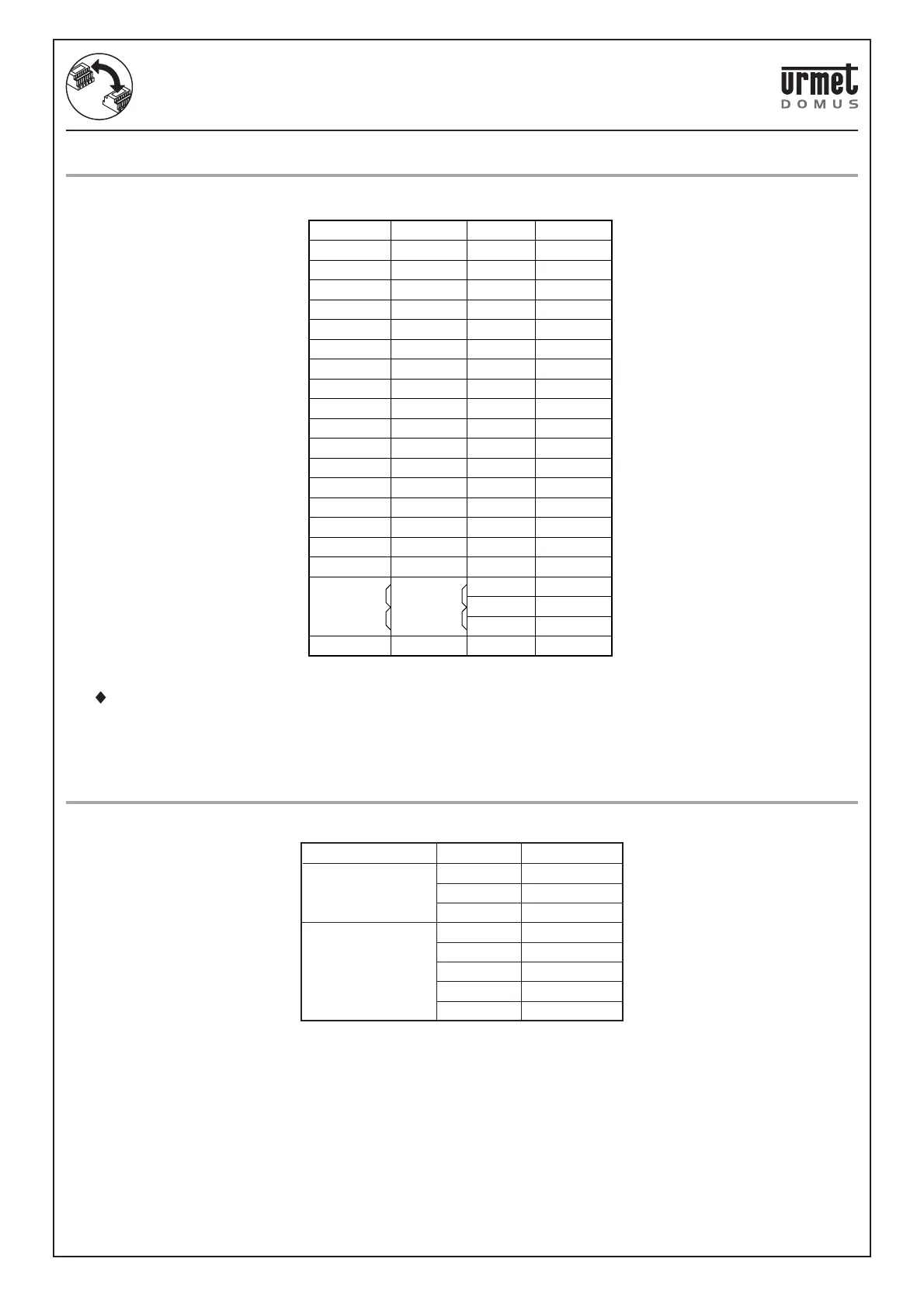
REPLACING RELAY BOXES Ref. 9332/1, Ref. 4330/31 AND Ref. 788/1 WITH Ref. 788/1
The Ref. 788/51 relay box can replace the obsolete 9332/1 model.
The terminals correspond as follows:
Note
: Terminals C1, C2, ~12 of relay Ref. 788/51 must be connected together by jumpers and connected to ~12.
Note ∗: Terminal not present in Ref. 9332/1 and Ref. 788/51. Add power wire ~0.
REPLACING SUPPLEMENTARY VIDEO DOOR PHONE POWER UNIT Ref. 7073/5A WITH
Ref. 789/2
The Ref. 789/2 power unit can replace the obsolete Ref. 7073/5 model.
The terminals correspond as follows:
Ref. 4330/31 Ref. 9332/1 Ref. 788/1 Ref. 788/51
2P
2S
4P
4
4S
AP/P
AP
AP/S
3P
3
3S
.
.
.
PUL/P
PUL/P
♦ A
B
2
1
3
4
5
6
7
8
9
10
11
12
15
13
14
SN1
SN2
♦ SN
∗
2
1
3
4
5
6
7
8
9
10
11
12
15
13
14
SN1
SN2
C1
C2
~12
~0
2
1
3
4
5
6
7
8
9
10
11
12
15
13
14
SN1
SN2
C1
C2
~12
~0
2
Ref. 7073/5 Ref. 789/2
~110
~230
R2 in
R2 out
RL
R1
V2
0
Not available
~230
R2 in
R2 out
RL
R1
V2
0
OUTPUTS
POWER