SECTION 5 – SWING DRIVE
3120933 Rev. 0 USTC 5-3
2. Apply low air pressure (20-30 psi) to the brake
release port while holding one hand on top of the
piston and springs. The air will force the piston
out of the case.
3. Remove friction pack. Friction pack consists of
friction discs, seperator plates and spacers.
Replace any items that are burned or scored.
4. Remove shaft from brake case by tapping out
the output end with a soft hammer.
Installation
Note: Unless otherwise specified, use automatic
transmission fluid (ATF) Type F as a lubricant for
the swing brake.
1. If removed, install shaft seal and bearing in the
case.
2. Install shaft in brake case. Tap shaft into place
with a soft hammer.
3. Install friction pack in the brake case. Install
spacer first and friction discs and spacers.
Note: Be careful not to contaminate friction surfaces
with dirt, grease or fluids other than those specified
for the brake.
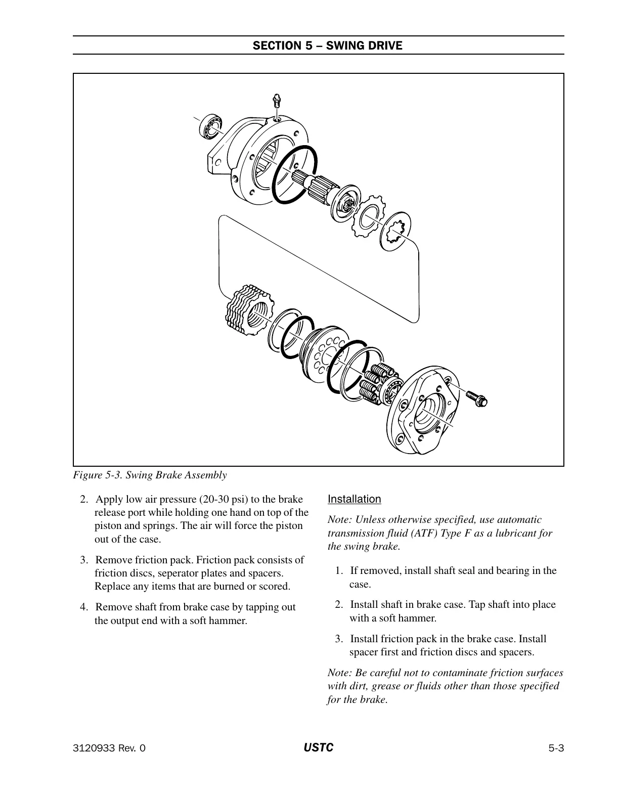
Figure 5-3. Swing Brake Assembly
Courtesy of Crane.Market