SECTION 7 – HYDRAULICS
3120933 Rev. 0 USTC 7-3
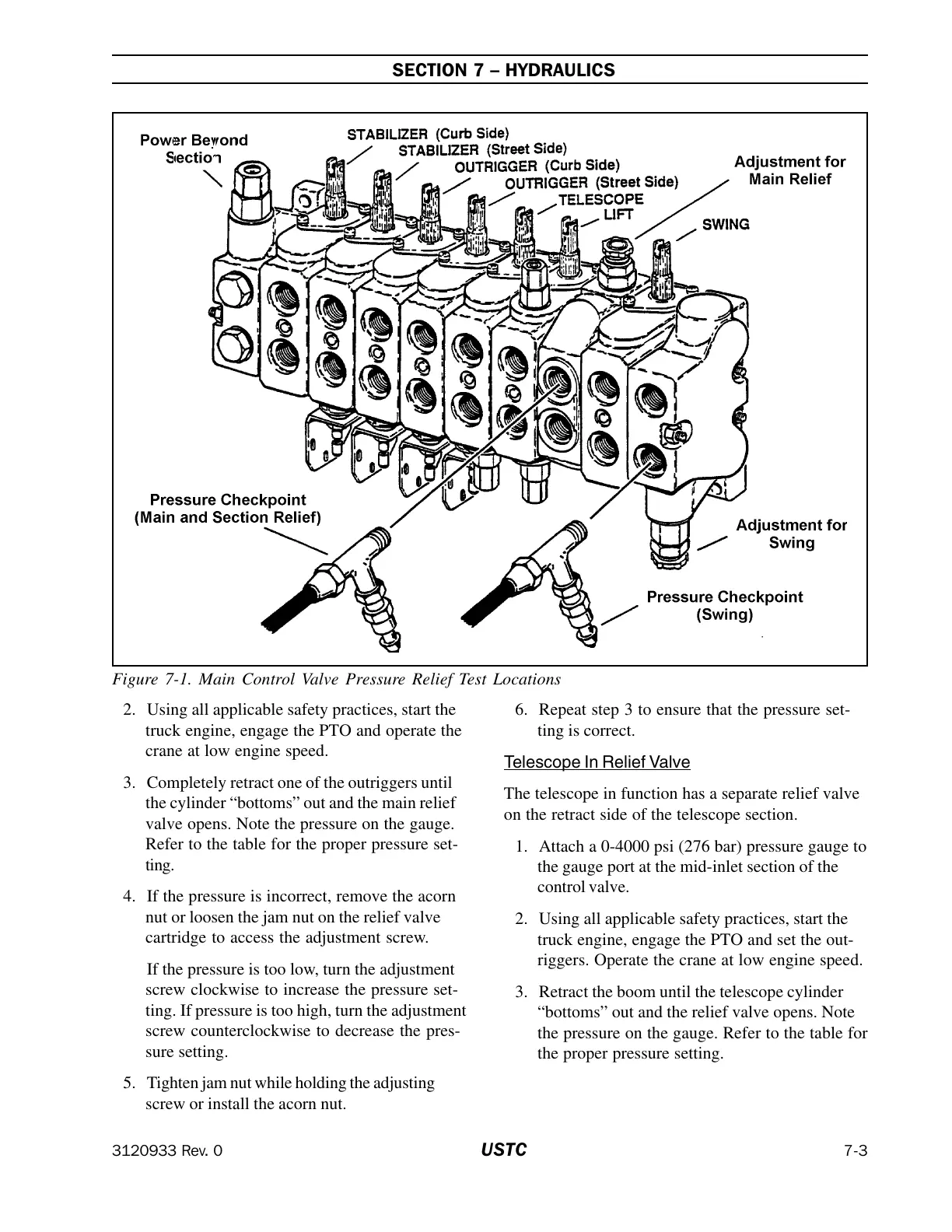
Figure 7-1. Main Control Valve Pressure Relief Test Locations
2. Using all applicable safety practices, start the
truck engine, engage the PTO and operate the
crane at low engine speed.
3. Completely retract one of the outriggers until
the cylinder “bottoms” out and the main relief
valve opens. Note the pressure on the gauge.
Refer to the table for the proper pressure set-
ting.
4. If the pressure is incorrect, remove the acorn
nut or loosen the jam nut on the relief valve
cartridge to access the adjustment screw.
If the pressure is too low, turn the adjustment
screw clockwise to increase the pressure set-
ting. If pressure is too high, turn the adjustment
screw counterclockwise to decrease the pres-
sure setting.
5. Tighten jam nut while holding the adjusting
screw or install the acorn nut.
6. Repeat step 3 to ensure that the pressure set-
ting is correct.
Telescope In Relief Valve
The telescope in function has a separate relief valve
on the retract side of the telescope section.
1. Attach a 0-4000 psi (276 bar) pressure gauge to
the gauge port at the mid-inlet section of the
control valve.
2. Using all applicable safety practices, start the
truck engine, engage the PTO and set the out-
riggers. Operate the crane at low engine speed.
3. Retract the boom until the telescope cylinder
“bottoms” out and the relief valve opens. Note
the pressure on the gauge. Refer to the table for
the proper pressure setting.
Courtesy of Crane.Market