SECTION 7 – HYDRAULICS
7-2 USTC January 15, 2001
Lift Cylinder
1. Activate hydraulic system and set outriggers
and stabilizers.
2. Position boom in horizontal position over rear
of truck.
Note: Tape measure or cord should be at least seven
(7) feet long for use in this test.
3. Attach tape measure or cord (at least 30 feet
long) to bottom of hook block.
WARNING: BEFORE RAISING AND
EXTENDING BOOM, ENSURE THAT AREAS
ABOVE AND BELOW BOOM AND HOOK
BLOCK ARE CLEAR OF ALL
OBSTRUCTIONS AND PERSONNEL.
4. Raise boom to a 15° elevation. Fully extend
boom.
5. Shut down hydraulic system by disengaging
Power-Take-Off (PTO) and turn off truck en-
gine.
6. With engine off, move boom control lever for-
ward.
If boom starts to lower, holding valve is defec-
tive and requires replacement.
If boom does not lower, complete steps 7
through 10.
CAUTION: HYDRAULIC LINES AND
PORTS SHOULD BE CAPPED IMMEDIATELY
AFTER DISCONNECTING LINES TO AVOID
ENTRY OF CONTAMINANTS INTO THE
SYSTEM.
7. Tag and carefully disconnect hydraulic lines to
lift cylinder. Use a suitable container to retain
any residual hydraulic fluid. Cap lines and
ports.
8. Note position of tape or cord and its position on
the ground. Mark as necessary. Leave boom
elevated in test position for approximately one
hour.
9. Check to see whether boom has lowered more
than eight inches.
If boom has lowered and oil is leaking around
rod-end cap of cylinder, seals in cylinder are
defective and require replacement.
If boom has lowered and oil is leaking from the
holding valve, the valve is either improperly
adjusted or defective and requires replacement.
CAUTION: ENSURE THAT HYDRAULIC
LINES ARE CONNECTED PROPERLY.
10. Connect hydraulic lines to lift cylinder.
PRESSURE TESTING
Several relief valves protect against overloading
different hydraulic circuits. Each relief valve should
be checked when setting up the machine or if lift
power seems too high or too low. Refer to the table
for specific settings for each relief valve.
Main Relief Valve
The main relief valve protects the lift, telescope out,
outrigger and stabilizer circuits.
1. Attach a 0-4000 psi (0-276 bar) pressure gauge
to the gauge port at the mid-inlet section of the
control valve.
TNENOPMOC
ERUSSERP
ISPGNITTES
)RAB(
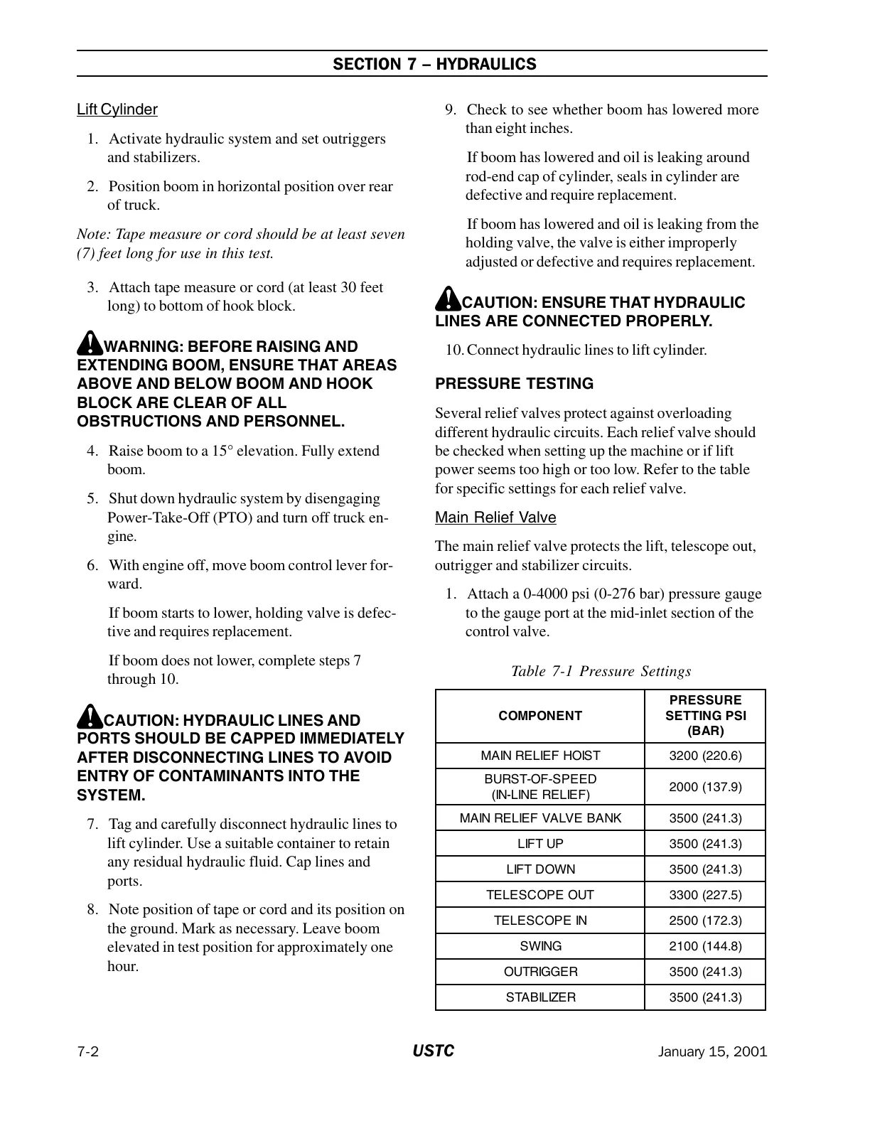
TSIOHFEILERNIAM)6.022(0023
DEEPS-FO-TSRUB
)FEILERENIL-NI(
)9.731(0002
KNABEVLAVFEILERNIAM)3.142(0053
PUTFIL)3.142(0053
NWODTFIL)3.142(0053
TUOEPOCSELET)5.722(0033
NIEPOCSELET)3.271(0052
GNIWS)8.441(0012
REGGIRTUO)3.142(0053
REZILIBATS)3.142(0053
Table 7-1 Pressure Settings
Courtesy of Crane.Market