SECTION 7 – HYDRAULICS
7-4 USTC January 15, 2001
4. If the pressure is incorrect, remove the acorn
nut or loosen the jam nut on the relief valve
cartridge to access the adjustment screw.
If the pressure is too low, turn the adjustment
screw clockwise to increase the pressure setting.
If pressure is too high, turn the adjustment
screw counterclockwise to decrease the pres-
sure setting.
5. Tighten jam nut while holding the adjusting
screw or install the acorn nut.
6. Repeat step 3 to ensure that the pressure setting
is correct.
Swing Inlet Relief Valve
The swing section has a separate relief valve in the
swing inlet section.
1. Attach a 0-4000 psi (0-276 bar) pressure gauge
to the gauge port at the mid-inlet section of the
control valve.
2. Remove the hydraulic line to the swing brake
and plug the line.
3. Using all applicable safety practices, start the
truck engine, engage the PTO and operate the
crane at low engine speed.
4. Move the swing control lever in either direction
and note the pressure reading on the gauge.
5. If the pressure is incorrect, remove the acorn
nut or loosen the jam nut on the relief valve
cartridge to access the adjustment screw.
If the pressure is too low, turn the adjustment
screw clockwise to increase the pressure setting.
If pressure is too high, turn the adjustment
screw counterclockwise to decrease the pres-
sure setting.
6. Tighten jam nut while holding the adjusting
screw or install the acorn nut.
7. Repeat step 4 to ensure that the pressure set-
ting is correct.
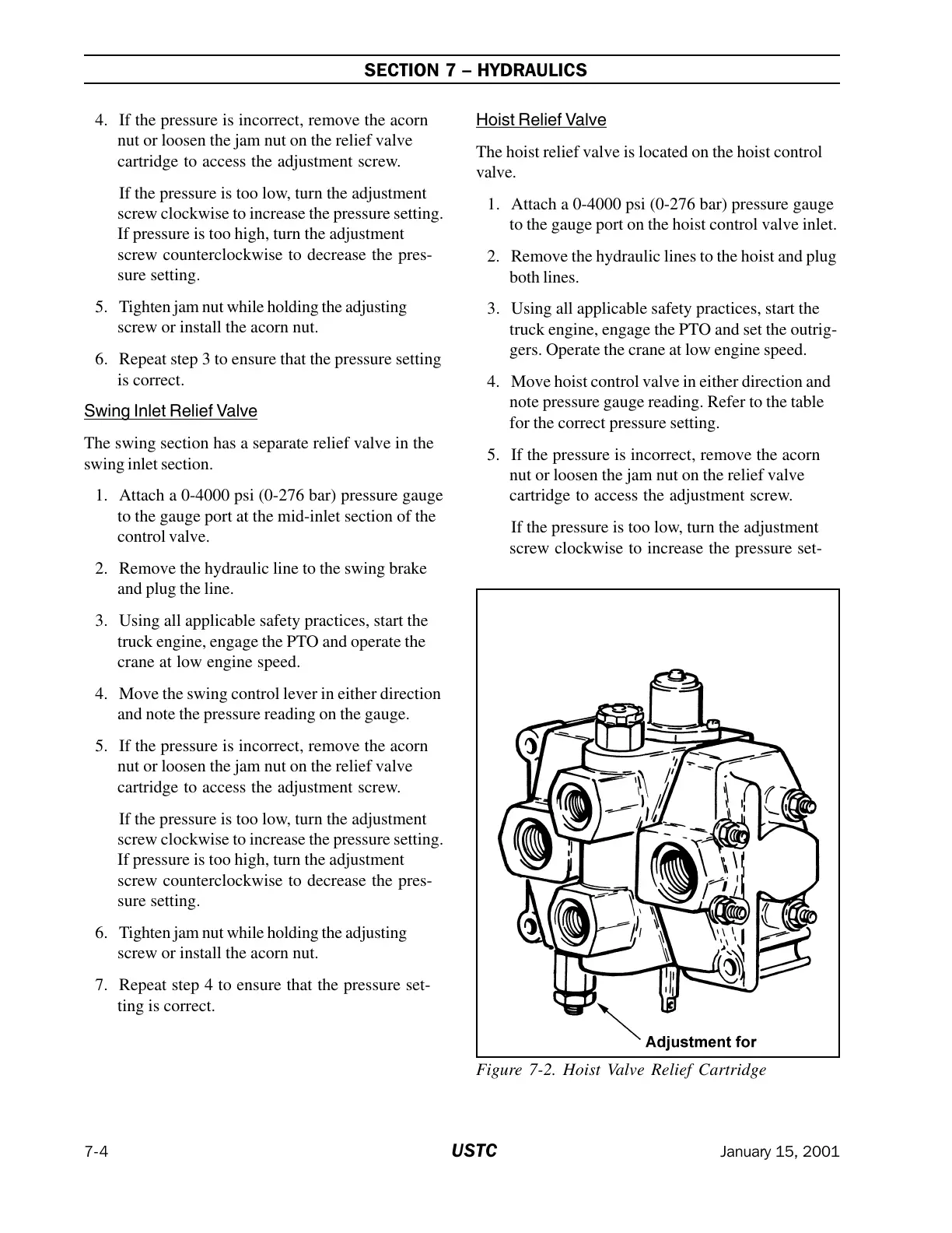
Hoist Relief Valve
The hoist relief valve is located on the hoist control
valve.
1. Attach a 0-4000 psi (0-276 bar) pressure gauge
to the gauge port on the hoist control valve inlet.
2. Remove the hydraulic lines to the hoist and plug
both lines.
3. Using all applicable safety practices, start the
truck engine, engage the PTO and set the outrig-
gers. Operate the crane at low engine speed.
4. Move hoist control valve in either direction and
note pressure gauge reading. Refer to the table
for the correct pressure setting.
5. If the pressure is incorrect, remove the acorn
nut or loosen the jam nut on the relief valve
cartridge to access the adjustment screw.
If the pressure is too low, turn the adjustment
screw clockwise to increase the pressure set-
Figure 7-2. Hoist Valve Relief Cartridge
Courtesy of Crane.Market