2HL/2HM/2HN
2-3-1
2-3 Operati on of the PWBs
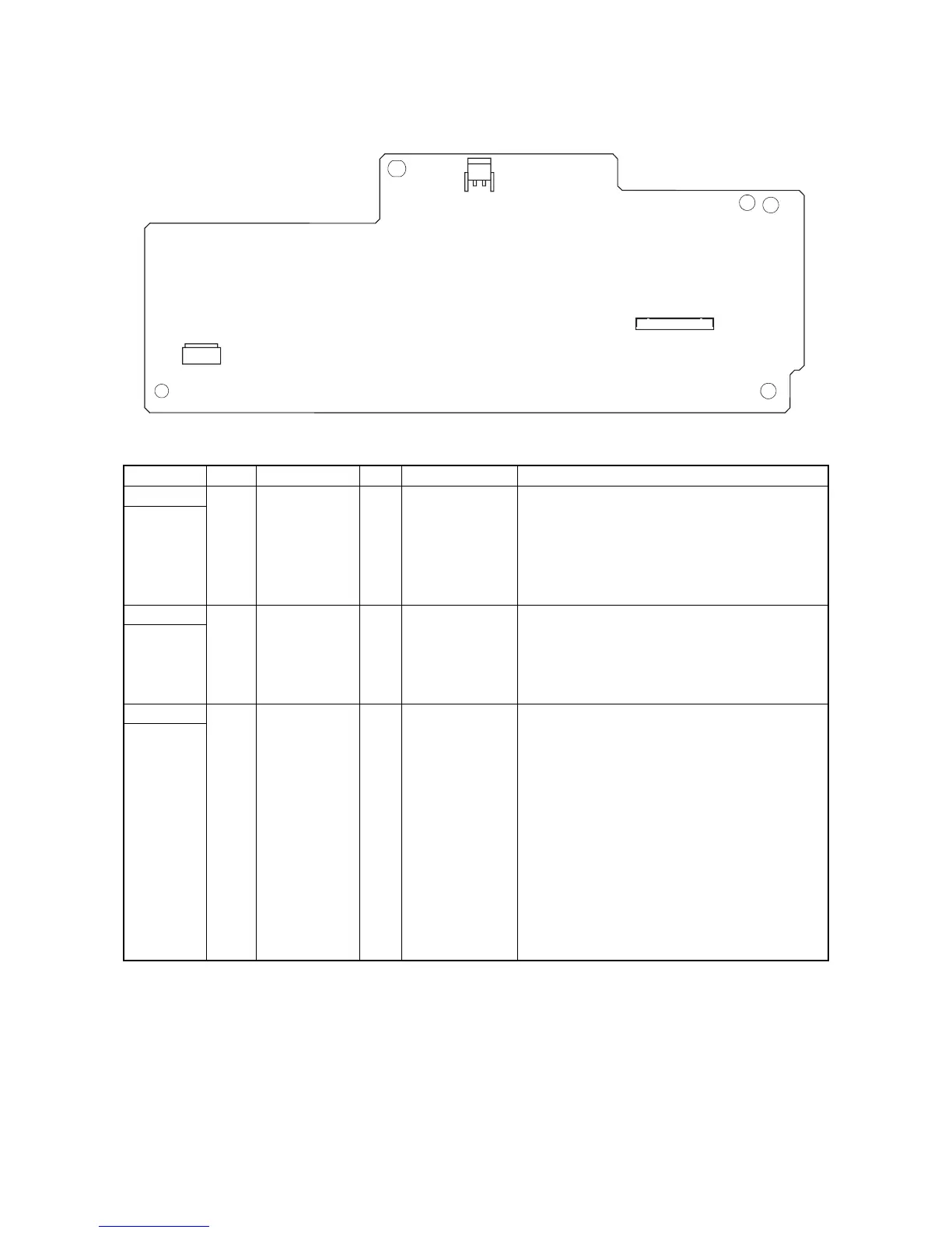
2-3-1 Power source PWB
Figure 2-3-1 Power source PWB silk-screen diagram
Connector Pin Signal I/O Voltage Description
YC101 1 LIVE I 120 V AC AC power input
Connected
to the AC
inlet and
power
switch.
220 - 240 V AC
2 NEUTRAL I 120 V AC AC power input
220 - 240 V AC
YC102 1 NEUTRAL O 120/0 V AC Fuser heater lamp: On/Off
Connected
to the fuser
heater lamp.
220 - 240/0 V AC
2 N.C. - - Not used
3 LIVE O 120 V AC AC power output
220 - 240 V AC
YC103 1 HEATREM I 24 V DC Fuser heater lamp: On/Off
Connected
to the
engine
PWB.
2 N.C. - - Not used
3 ZCROSS O 0/3.3 V DC (pulse) Zero-cross signal
4 SLEEPN I 0/24 V DC Sleep mode signal: On/Off
5 +24V3 I 24 V DC 24 V DC power source
6 GND - - Ground
7 GND - - Ground
8 GND - - Ground
9 GND - - Ground
10 +24V1 O 24 V DC 24 V DC power source
11 +24V1 O 24 V DC 24 V DC power source
12 +24V1 O 24 V DC 24 V DC power source
13 +24V1 O 24 V DC 24 V DC power source
1
YC101
YC103
YC102
1
1