G
Gregory TapiaAug 13, 2025
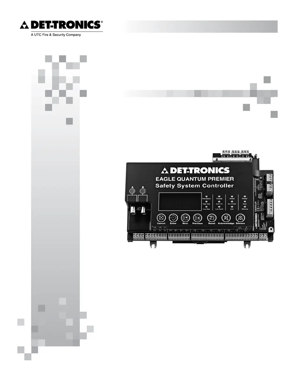
What to do if the Trouble Relay is active in UTC Fire and Security Controller?
- KKaren GriffinAug 14, 2025
If the Trouble Relay is active, it indicates that a monitored device in the system, including a ground fault, is in a fault condition. Use the front panel display/controls to view all points in alarm/fault and identify the faulted device. Then, repair or replace the faulted device as necessary.