54 Remote Booster Power Supply Technical Reference Manual
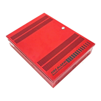
CDR-3 Coder to Genesis notification
Figure 40: CDR-3 Coder to Genesis notification
G
G
(11)
G
GG
GG
GG
(12)
(1)
(2)
(3)
(4)
BPS
(7)
(8)
(9)
(10)
(5)
(6)
Legend
(1) NAC visible circuit
(2) NAC/CDR-3 audible circuit
(3) Sense 1
(4) Sense 2
(5) Mode: GM
(6) NACs: CONT
(7) NAC1
(8) NAC 2
(9) NAC 3
(10) NAC 4
(11) To next BPS, or EOL resistor
(12) To next device or EOL resistor
Notes
• In order for the audible appliances to follow the CDR-3 coder signals, you must modify each
Genesis audible-capable appliance that is connected to a coded NAC. For Genesis G1
Series appliances cut open Circle. For Genesis WG4 horns & horn/strobes, cut jumper
JP4. For Genesis GC(F)-HDVM(H) appliances, cut JP1.
• The maximum number of BPSs that can be connected on a single NAC from sense circuit to
sense circuit is limited by available current and wire run length.
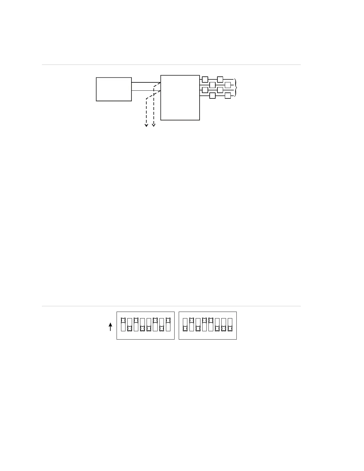
DIP switch settings for this application
BPS DIP switches can be set this way for the application to work correctly. Refer
to “Setting the DIP switches” for other options.
Figure 41: Switch settings
SW1 SW2
1234
5
6
7
8
ON
1234
5
6
7
8