Do you have a question about the UTICA BOILERS CCB-150 and is the answer not in the manual?
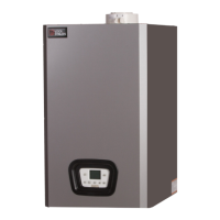
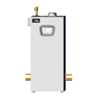
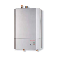
Details specific models: CCB-150 Combi and CHB-100/CHB 130 Heating Only.
Lists common features across all CuB boiler models, including efficiency and operational capabilities.
Details features of the CCB-150 model, including DHW production and capacity.
Presents technical data for CCB150, CHB130, and CHB100 models in a table format.
Provides required clearance dimensions for combustible materials and service access.
Identifies and describes major internal components of the boilers.
Highlights specific components of the Combi boiler, including DHW heat exchanger.
Diagram showing main components of the CCB 150 with labels.
Illustrates the plumbing circuit for the CCB 150 model with numbered components.
Illustrates the plumbing circuit for CHB-100/130 models with numbered components.
Instructions for connecting CHB models to an indirect tank using the DHW Sensor Kit.
Procedure for installing the DHW storage tank sensor and changing parameter P02.
Detailed steps for connecting to an indirect tank and setting parameter P02.
Diagram showing bottom view of CCB 150 with labeled water and fuel connections.
Diagram showing CHB series connections for piping to an indirect tank.
Details the safety relief valve, its pressure rating, and installation warning.
Specifies materials and standards for vent pipe and combustion air fittings.
Details horizontal venting requirements, including appliance adapters and increasers.
Illustrates supplied and field-sourced components for combustion air and venting.
Diagrams show different venting configurations: Two Pipe, Chimney Venting with Room Air, and Outside Air.
Diagram of termination assembly for venting, showing components and connections.
Describes the heating system water pressure switch and its fault conditions.
Explains the flow meter's role in sensing water flow and adjusting firing rate.
Presents pump head vs. flow rate curves and notes pump group features.
Illustrates the 3-way diverter valve in Central Heating and DHW modes.
Details how the 3-way valve operates via a stepper motor and anti-sticking protection.
Explains the 120 Vac fan operation and the Venturi's role in pressure sensing.
Describes how the air pressure transducer signals the PCB to drive the fan based on chimney conditions.
Explains the process of controlling air and gas flow for optimized combustion.
Presents a chart showing the relationship between temperature and resistance for NTC sensors.
Diagrams showing the location of CH and DHW NTC sensors within the CCB 150.
Details thermostat wiring and LWCO connections to the terminal blocks.
Provides a detailed wiring diagram for the CCB 150 model.
Presents the ladder diagram for the CCB 150, showing component interconnections.
Provides a detailed wiring diagram for the CHB 100/130 models.
Explains the ignition attempt sequence for Natural Gas and LP Gas boilers.
Describes the gas valve as a positive pressure, fully modulating design.
Identifies minimum and maximum adjustment points on the gas valve.
Details how to sample gas supply pressure and lists pressure specifications.
Procedure for checking natural gas combustion, including input calculation and orifice sizes.
Instructions for initial steps in LP conversion, involving cover removal.
Instructions for further LP conversion steps, including burner assembly and orifice changes.
Identifies all buttons, symbols, and displays on the boiler's control panel.
Explains how to switch the boiler on/off using the ECO/COMFORT button.
Describes the display in standby mode and the boiler's readiness for calls.
Details FH mode, its duration, and component actions for air purging.
Provides instructions on how to skip the FH mode sequence.
Explains how to activate ECO and Comfort modes and their effects on DHW preheating.
Instructions for activating Summer mode, which prevents boiler operation.
Describes the boiler's actions when the temperature sensor is below 41°F.
Explains DHW mode, tap icon activation, and display of burner power.
Highlights how the optional outdoor sensor enables reduced water temperature for fuel savings.
Instructions for setting the outdoor sensor curve, including CU flashing and value entry.
Presents Outdoor Temperature Compensation (OTC) curves showing boiler flow temperature vs. outside air temperature.
Graphs illustrating parallel compensation curve shifts for different offsets.
Table providing resistance values for the NTC outdoor sensor at various temperatures.
Instructions for entering Test Mode for combustion testing and adjusting max power.
Guide to accessing and navigating the service menu (tS, In, Hi, rE).
Instructions on how to enter the tS menu and scroll through parameters.
Explains how to use DHW buttons to change values within the tS menu.
Lists parameters (P01-P18) for the CCB 150, their descriptions, and default values.
Guide to accessing and using the Information menu to view sensor values and operating data.
Instructions on how to scroll through and display fault history entries.
Explains the difference between 'A' faults (manual reset) and 'F' faults (auto reset).
Lists fault codes, their possible causes, and resolutions for common faults.
Continues the fault list with codes F39 through F51, including causes and resolutions.
Details configuration parameters, including curve selection for model identification.
Outlines the warranty terms: two years for all parts and ten years for the primary heat exchanger.
| Brand | UTICA BOILERS |
|---|---|
| Model | CCB-150 |
| Category | Boiler |
| Language | English |