17
LIGHTING PROCEDURE FOR BOILER WITH
INTERMITTENT PILOT SYSTEM
STOP!
1.
Read the safety information in the user’s informa-
tion manual.
Set thermostat to lowest setting.
2.
Turn off all electric power to the appliance.
3.
This appliance is equipped with an ignition device which
4.
automatically lights the burner. DO NOT try to light the
burner by hand.
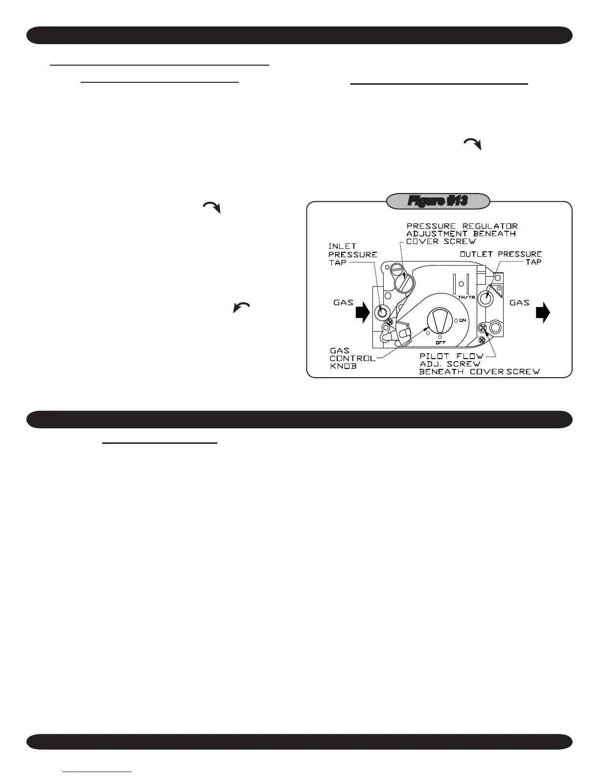
Turn the gas control knob clockwise
5.
to “OFF”. (See
Figure #13
)
Wait ve (5) minutes to clear out any gas. Then smell for
6.
gas, including near the oor. If you smell gas,
STOP!
Follow “What To Do If You Smell Gas” in the safety infor-
mation section. If you don’t smell gas, go on to the next
step.
Turn the gas control knob counterclockwise
7.
to “ON”.
Turn on all electrical power to the appliance.
8.
Set the thermostat to desired setting.
9.
If the appliance will not operate, follow the instructions “To
10.
Turn Off Gas To Appliance” and call your service techni-
cian or gas supplier.
TO TURN OFF GAS TO APPLIANCE
Set the thermostat to lowest setting.
1.
Turn off all electric power to the appliance if service is to
2.
be preformed.
Turn gas control knob clockwise
3.
to “OFF” Do Not
Force.
ON A CALL FOR HEAT:
The thermostat will actuate, completing the circuit be-
1.
tween terminals T and T.
The R8222C relay coil will energize thus pulling in the
2.
relay contacts.
The circulator starts and power is switched to the limit.
3.
If limit circuit is closed the venter motor and TF-2 trans-
former are energized.
The venter motor starts and develops static pressure.
4.
When the static pressure is reached the pressure switch
5.
pulls in completing the circuit between TF-2 and the inter-
mittent ignition control.
The intermittent ignition control opens the pilot valve
6.
and ignites pilot. After pilot is proven the main burner will
ignite.
In the event the boiler water temperature exceeds the
7.
high limit setting the power will be interrupted to the ven-
ter motor, and TF-2 thus interrupting power to the ignition
system. Power will remain off until the water temperature
drops below the high limit setting. The circulator will con-
tinue to operate under this condition until the thermostat is
satised.
Should the air ow (static pressure) be interrupted (ex-
8.
ample blocked ue, etc.), the pressure switch will sense a
drop in pressure, opening the circuit between the igni-
tion system and TF-2. The venter motor will continue to
operate until static pressure is reached or thermostat is
satised.
In the event the ow of combustion products through
9.
any part of the boiler ueway becomes blocked, a ame
safety roll-out switch will shut off the main burners. If this
condition occurs, do not attempt to place the boiler back
operation.
When the thermostat is satised power is interrupted to
10.
the relay coil and the relay drops out cutting power to the
circulator, venter motor, and TF-2.
LIGHTING INSTRUCTIONS
SEQUENCE OF OPERATIONS
Figure #13